ESTE: Pulse Width Modulation (PWM)
This experiment is part of this project.
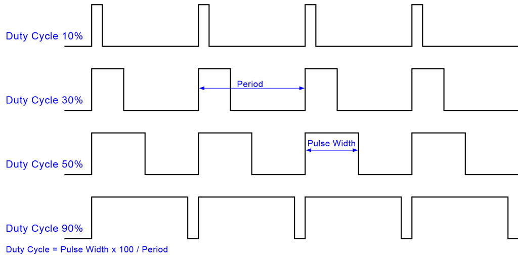
Here we are going to build an experiment with an led to learn and start using the PWM. PWM is called Pulse Width Modulation, and it is basically a technique used in many areas of electronics, perhaps the most common is the use in switching power supplies but can also be used for motor speed control, light control, servo motor control and many other applications. Here we will use the PWM functionality to control the light intensity of one led. Before we start it is necessary to know the two essential configurations of the PWM. Practically, what we do with the PWM, is to configure the pulse width - the period a wave stays high - and the frequency in wich we want the signal to operate - how fast or how slow will be the pulse width. Therefore to configure the pulse width we use the “duty cycle” parameter and to configure the frequency he use the signal’s frequency parameter. The duty cycle is given as a percentage of the signals period, on wich the signal is high (Duty Cycle = Pulse Width x 100 / Period) and is set on a microcontroller by storing the duty value in a register (duty value from 0 - 0% to 256 - 100% in 8 bits registers and from 0 - 0% to 1024 - 100% in 16 bits registers).

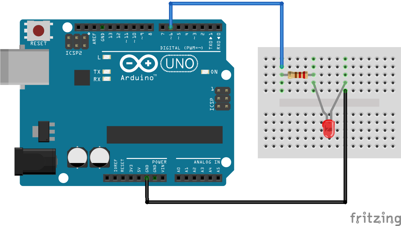
The frequency parameter of the generated signal is set on the microcontroller by dividing its timers clock frequency with prescalers as commonly 1, 8, 64, 256 and 1024. Per example, if the clock frequency of the microcontroller is 16MHz and dividing it by the prescaler 1, the signal frequency will be 16MHz - consequently the pulse width will be really fast- and dividing it by the maximal prescaler of 1024, the signal frequency will be 16KHz - consequently the pulse width will be more slow. Finally, to apply the PWM functionality on the digital signal that will control the LED light, we need to connect the led on digital pins that already are configured to use the pwm and they are D3, D5, D6, D9, D10 and D11.
1 Pseudo code
Let's begin with a solution. The pseudo code (actual coding is up to you) is below:
int main(void) {
    led_light(pin, 0);                    //set here, in the beginning, the led off
    while(1) {
	set_pwm_frequency(1);
	set_dutycycle(128);
	delay(5000);
	set_pwm_frequency(1024);
	delay(5000);
/*during the loop you can call the set_duty_cycle() and the set_pwm_frequency(), as many times you want, to see the differences between each signal generated*/
    }
    return 0;
}

set_duty_cycle(value){
    dutycycle_register = value;
}

set_pwm_frequency(divisor){
    timer_clock_register = divisor;
}
This pseudo-code has a loop in wich we call the functions to set the duty cycle (correspondent to the light intensity we want) and the frequency that the pulse width will work with. As commented in the code, after setting those parameters, wait a little before going into the loop again and you will see the results of the generated signal and the LED light control. It is also really useful to use an oscilloscope to verify the digital signal generated on the PWM pins.
2 Schematic

3 Part List
- 1 LED
- 1 220 ohm resistor
- 1 Protoboard
- 2 copper wires (tinned) or jumpers
4 Assembly

5 Solutions
6 Tools
- AVR GCC and tools
- Arduino IDE
- Oscilloscope
7 Media
8 References
- EccoSaver - O que é PWM?
- Aberto de madrugada- O que é o PWM?
- MecaWeb- PWM, Modulação Por Largura de Pulso
- Arduino Reference - PWM
- LabdeGaragem - Video tutorial PWM
- Eletrônica Fácil - Video tutorial sinal PWM
- Embarcados - Arduino e saídas PWM
- WikiSpaces - Changing PWM Frequency on the Arduino
- Arduino Learning - Secrets of Arduino PWM
- Arduino Learning - Timer PWM Cheatsheet
- Arduino Learning - Pwm Frequency
- QEEWiki - PWM On The ATmega328
- GarretLab - analogWrite()
- Extreme Eletronics - PWM Signal Generation by Using AVR Timers
- MaxEmbedded - AVR Timers and PWM Mode
- ErmicroBlog - Working with Atmel AVR PWM
- How To Change Frequency On PWM Pins Of Arduino UNO