ESTE: GPIO and External Interrupts - part 1
This experiment is part of this project.
Here we are going to build a experiment with an led and a push button, using the GPIO to consolidate concepts of interrupts. A interruption is an action performed by the microcontroller that allows itself to stop doing what is being performed at the time and immediately answer the device requesting the interruption. There are two types of Interrupts requests: called from the hardware (external signal) and from the software (programming code). At this moment we are going to work with the external interrupt. Before we begin it is essential to know that external interrupts are called by hardware components, whose signal generated (HIGH and LOW) varies very fast. In order to perform an interrupt call that is regular and accurate, it’s signal must undergo a treatment that is basically the determination of a time limit to regularize the signal call. This treatment is called deboucing. The exercise here proposed is to turn on and off a led each time we press the push button. To complete this experiment it is recommended to see at first the GPIO script.
1 Pseudo code
Let's begin with a solution. The pseudo code (actual coding is up to you) is below:
interrupt_source = 0;        //you can select two interrupt sources: 0 (pin 2) and 1 (pin 3)
led_state = 0;               //state = 0, led is off; state = 1, led is on
debounce_limit = 200;        //limit time in ms between interrupts to debounce the electric signal
sensitivity = HIGH;          //select signal event that generates interrupt (SIGNAL_HIGH, SIGNAL_LOW, SIGNAL_CHANGE, RISING_EDGE, FALLING_EDGE)

int main(void) {
    while(1) {
        led_value(led_state);
    }
}

void interrupt_handler(){
    if (debounce())
        led_state = !led_state;
}

int debounce(){
    //debounce is the function responsible for stabilizing the interruption requests

    if( (now - time_last_accepted_interrupt) > debounce_limit) {
        time_last_accepted_interrup = now;
        return 1;
    }
    else
        return 0;
}
This pseudo-code always send a led_state to the led so that it atualizes his brightness acording to the states on and off. When the signal in the selected interrupt_source has the value defined by sensitivity, the microcontroller generates an interrupt that is handled by the function interrupt_handler. To truly perform a led change, i.e the interrupt_handler, it is necessary to check if the debounce was done correctly, because the debounce will treat all the calling signals to the interruption - commonly thousands of calls per second in a push button - so that they stay regular. After the treatment of the interrupt signals, the led_state will be changed, varying between on and off.
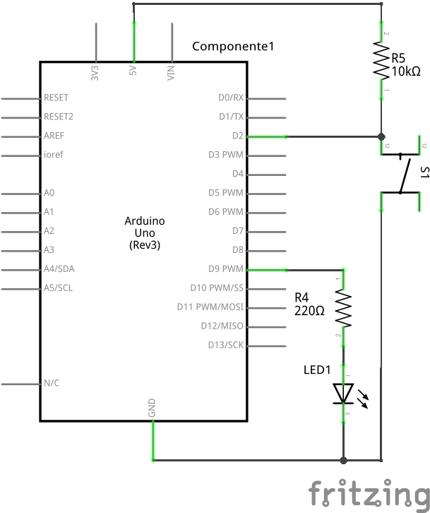
2 Schematic

3 Part List
- 1 LED
- 1 push button
- 1 10k ohm resistor to the button
- 1 220 ohm resistor to the led
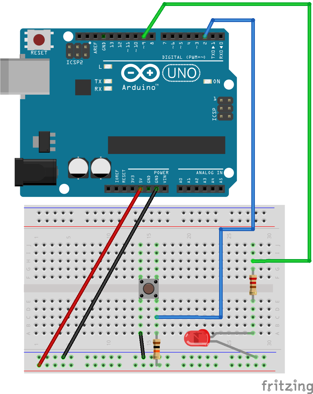
- 1 Protoboard
- 5 copper wires (tinned) or jumpers
4 Assembly

5 Solutions
6 Tools
- AVR GCC and tools
- Arduino IDE
7 References
- HumanHardDrive - Video tutorial: Arduino and external pin interrupts
- Arduino Reference: attachInterrupt()
- Stackexchange: correlated problems solving
- Davidorlo: Arduino - Interrupt Tutorial with LED & Switch
- Instructables: Arduino - Software debouncing
- Sparkfun: Processor Interrupts with Arduino
- Engblaze: Arduino interrupts
- Gonium: Handling external Interrupts with Arduino
- Embedds: Implementing AVR interrupts
- Embedds: Basic understanding of microcontroller interrupts