ESTE: Analog Temperature Sensor 2 (NTC - Negative Temperature Coeficient)
This experiment is part of this project.
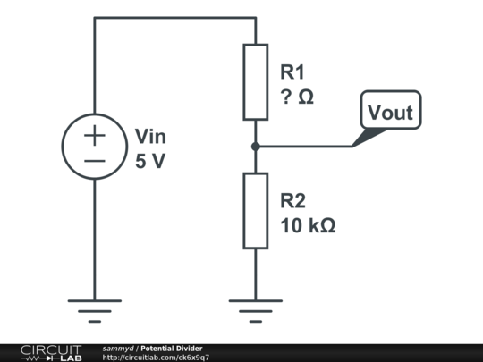
Here we are going to build one more experiment using the ADC and a temperature sensor, namely the thermistor NTC. Thermistors are resistors which are sensitive to heat and their electrical resistance changes as the temperature changes. There are tow types of thermistors: positive temperature coefficient (PTC) and negative temperature coefficient (NTC). In the PTC thermistors the resistance increases as the temperature increases, which is a useful property in safety systems. NTC - which are going to be used here - are the opposite, where the resistance decreases as the temperature increases. The relationship between temperature and resistance can be calculated through the Steinhart-Hart equation or the Beta equation. As the beta equation is easier to calculate this relationship on NTC thermistors, we will use it. The beta equation is the following: 1/T=1/T0+1/B x ln(R/R0) where T0 is the reference temperature of the thermistor (usually 298.15K - 25°C), B is the β value of the thermistor (available on the datasheet) and R0 is the resistance at the reference temperature. The NTC we’re using in our circuit has an internal resistance of 10kΩ (R0), at the reference temperature of 25°C (298.15K) and a B-value (β) of 3950. As we want to measure the final temperature T we will first need the R value, that can be obtained from a voltage divider as shown below:

Applying the Ohm’s law (V=IR) we derive the following equation for the final resistance: R1=R2⋅VinVout−R2 , where the R1 is our R and R2 our R0. The Vout or reading output may be connected to an Arduino in one of its analog inputs (ADC). The resistance R2/R0 of 10k ohms will not necessarily have this value. The value of this resistance should be as close as possible to the initial resistance of the NTC (use a multimeter to check). In order to understand all the concepts used in this experiment it is recommended to have seen at first the ADC and Sensor Reading and LDR scripts.
1 Pseudo code
The basic code of the solution for this experiment is shown and well explained on the Sensor Reading’s script. The following code is complementary for the temperature calculation:
int main(void) {
    int x;
    while(1) {
        Accumulate(x);
        RMS();
        Temperature();
    }
    return 0;
}

void Temperature(){
    res = (res0*5/V0) - res0;
    /* R = (R0.Vin)/Vout - R0 */

    TK =  1/T0 + (1/beta)*log(res/res0);
    TK = 1/TK;
    /* 1/T = 1/T0 + 1/B x ln(R/R0) */
    /*TK é a temperatura em kelvins, para adquirí-la em Celcius ou Fahrenheit e preciso realizar as conversões:
    TC = (TK - 273.15) e  TF = (TC*5/9 + 32)*/
}
This pseudo-code show some functions to perform: the accumulation necessary to the average; the calculation of a precise average (RMS); the conversion from analogic signal to digital values and back and the calculation of the both desired final resistance and temperature. The calculation of the final resistance R and the desired final temperature are calculated on the Temperature() function.
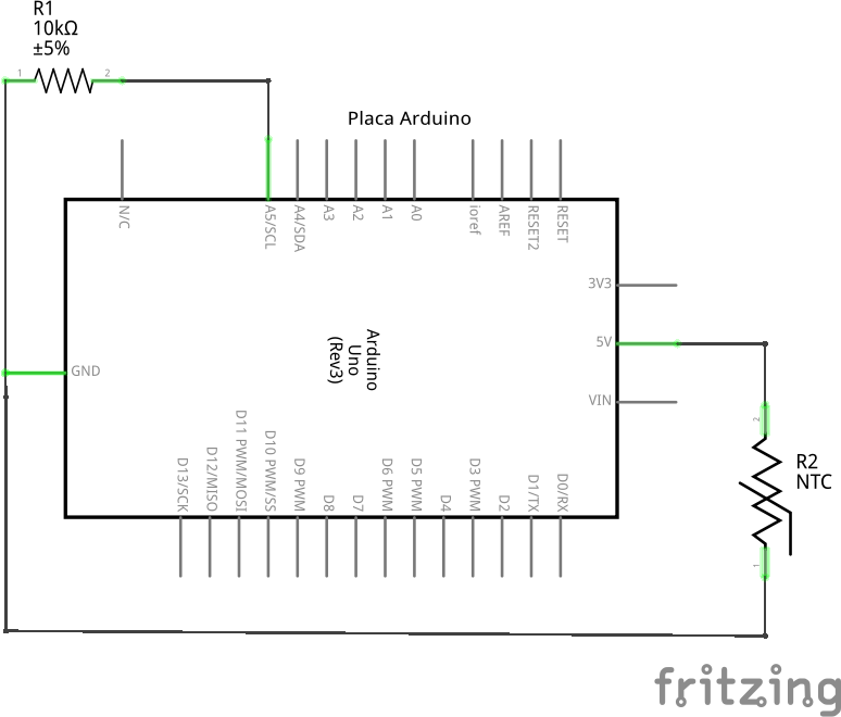
2 Schematic

3 Part List
- 1 NTC
- 1 10k ohm resistor
- 1 Protoboard
- 3 copper wires (tinned) or jumpers
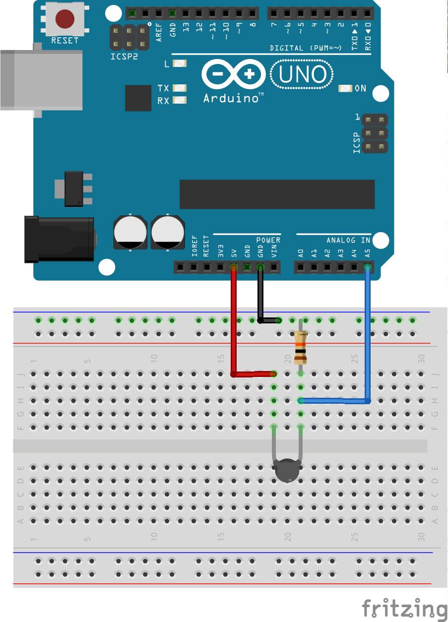
4 Assembly

5 Solutions
6 Tools
- AVR GCC and tools
- Arduino IDE