ESTE: Automatic Dimmer with PWM and ADC: mudanças entre as edições
Criou página com 'This experiment is part of this project. This experiment is based on contents of [http://www.lisha....' |
Sem resumo de edição |
||
| Linha 11: | Linha 11: | ||
<syntaxhighlight lang=c> | <syntaxhighlight lang=c> | ||
int main() { | int main() { | ||
set_point = 127; | |||
duty_cycle = 0; | |||
while(1) { | while(1) { | ||
light = adc->read(); | |||
if( | if (light > set_point && duty_cycle >= 0) | ||
duty_cycle = 0; | |||
else if (light <= set_point && duty_cycle <= 255) | |||
duty_cycle = adc->read(); | |||
pwm->write(duty_cycle); | |||
delay(); | |||
delay( | |||
} | } | ||
return 0; | return 0; | ||
} | } | ||
</syntaxhighlight> | </syntaxhighlight> | ||
The pseudo-code is self-explaining: an infinite loop reading the ADC channel to which the potentiometer has been connected and | The pseudo-code is self-explaining: an infinite loop reading the resistance value of the LDR Photoresistor (that indicates the ambient light), a composed conditional to switch on/off the LED according to the necessity of luminosity, and an ADC channel to which the potentiometer has been connected and determinates the light intensity of the LED. | ||
==Schematic== | ==Schematic== | ||
Edição das 10h22min de 24 de novembro de 2015
This experiment is part of this project.
This experiment is based on contents of this UFSC project.
Here we are going to build an experiment with an led and a LDR sensor and the same concepts seen on the Dimmer with PWM and ADC Script. Here we will use a potentiometer to turn 1 LED on and off, only if we need luminosity. To know how much luminosity(light) do we need in our surrounding we will use the LDR sensor, that indicates according to it's resistance, how should be the light intensity of the led. If our surrounding is to dark the specific led is turned on according to the potentiometer value. If it is bright enough, the led is turned off.
1 Pseudo code
Let's begin with a solution. The pseudo code (actual coding is up to you) is below:
int main() {
    set_point = 127;
    duty_cycle = 0;
    while(1) {
        light = adc->read();
        if (light > set_point && duty_cycle >= 0)
            duty_cycle = 0;
        else if (light <= set_point && duty_cycle <= 255)
            duty_cycle = adc->read();
        pwm->write(duty_cycle);
        delay();
    }
    return 0;
}
The pseudo-code is self-explaining: an infinite loop reading the resistance value of the LDR Photoresistor (that indicates the ambient light), a composed conditional to switch on/off the LED according to the necessity of luminosity, and an ADC channel to which the potentiometer has been connected and determinates the light intensity of the LED.
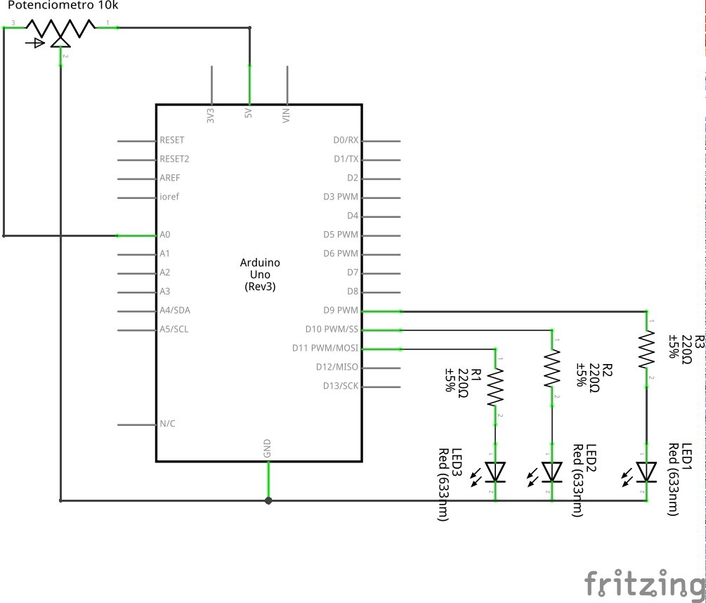
2 Schematic

3 Part List
- 3 LEDs
- 3 20 to 220 ohm resistors to the leds
- 1 10k potentiometer
- 1 Protoboard
- 7 copper wires (tinned) or jumpers
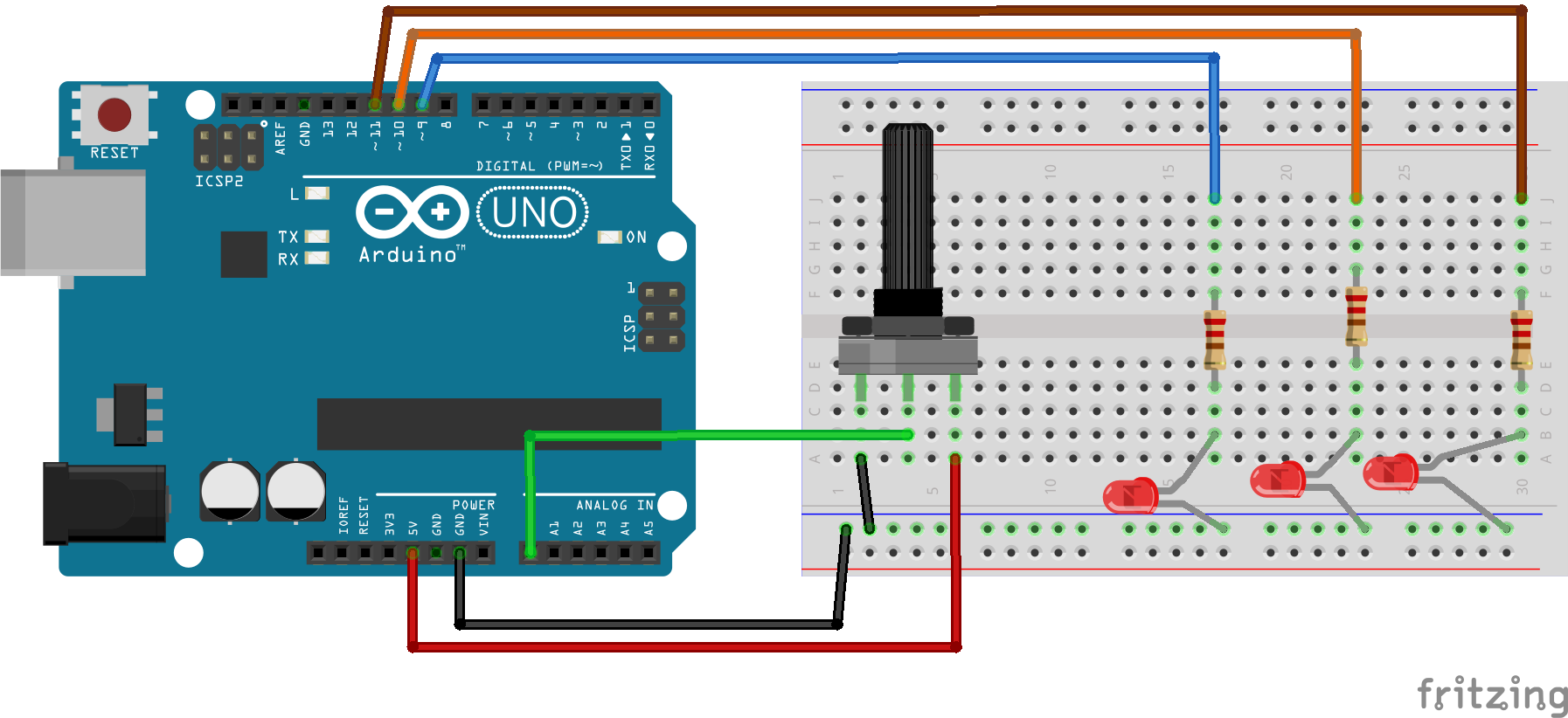
4 Assembly

5 Solutions
6 Tools
- AVR GCC and tools
- Arduino IDE