Transmissão digital em banda passante
Passband Modulation
This model shows a straightforward way to perform passband modulation, by multiplying a modulated complex signal with a complex sine wave to perform frequency upconversion. In general, it is preferable to model a system at complex baseband. However, there are some circumstances where it is necessary to model the system at real passband. . Mais informações [1].
Primeiramente baixe o arquivo a seguir Sistema.zip (O mesmo também pode ser encontrado em MATLAB/R20xxx/toolbox/comm/commdemos). Descompacte e certifique-se que no Matlab você esteja no diretório onde descompactou o arquivo. Digite no terminal do Matlab:
open_system('commpassbandmod')
Estrutura do exemplo
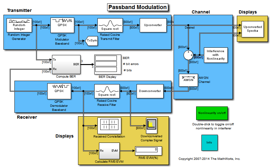
The communications link in this model includes these components:
- A Random Integer Generator block, used as source of random data
- A modulator and a pulse shaping filter that perform QPSK modulation and root raised cosine pulse shaping.
- An Upconverter block that multiplies the modulated signal by a carrier frequency.
- A source of tone interference. The interference has a cubic nonlinearity which may be toggled on or off. When the nonlinearity is off, the interference falls completely out of band, but when on, the third harmonic of the tone is introduced into the desired band, causing co-channel interference.
- An AWGN Channel block, set to Eb/No mode. It specifies two bits per symbol because the modulation format is QPSK. The signal power is 1/(2*8) watts. This is because the original signal power at the modulator is 1 watt. The root-raised cosine filter upsamples the signal by a factor of 8, which reduces the power by that factor. The frequency upconversion block output takes only the real part of the signal, thereby reducing the power again, this time by a factor of 2. Finally, the symbol period is 1e-6 seconds, to match the original sample time on the Random Integer Generator source.
- A Downconverter block that converts the signal from real passband to complex baseband.
- A root raised cosine pulse shaping filter that decimates back to one sample per symbol, and a QPSK demodulator block.
- BER and RMS EVM metric calculation blocks.
Toolbox e blocos necessários
Para realização da simulação, é necessário o Communications System Toolbox™ fornecido pelo próprio Simulink. O exemplo é realizado de acordo com o seguinte diagrama de blocos:
- Random Integer Generator;
- QPSK Modulator Baseband;
- Goto;
- Raised Cosine Transmit Filter;
- Upconverter (Subsystem);
- Sum;
- Interference (Subsystem);
- Upconverted Spectra (Subsystem);
- AWGN Channel;
- Downconverter (Subsystem);
- QPSK Demodulator Baseband;
- Compute BER (Subsystem);
- Display;
- Constellation Diagram;
- Calculate RMS EVM (Subsystem);
- Spectrum Analyzer;
Subsistemas
- Upconverter
- Inport
- Sine Wave
- Product
- Complex to Real-Imag
- Outport
- Interference
- Sine Wave
- Constant
- Math
- Gain
- Complex to Real-Imag
- Outport
- Upconverted Spectra
- Inport
- Concatenate
- Spectrum Analyzer
- Downconverter
- Inport
- Sine Wave
- Product
- Math (conj)
- Outport
- Compute BER
- Inport
- Error Rate Calculation
- Integer to Bit Converter
- Constant
- Outport
- Calculate RMS EVM
- Goto
- Delay
- Inport
- Outport
- EVM Measurement
Testes que podem ser feitos
Os testes foram realizados nas versões 2012a, 2014a e 2015a do software Matlab, funcionando perfeitamente nas mesmas. A seguir alguns testes que podem ser feitos com este modelo.
