Mudanças entre as edições de "Interfaces de entrada e saída da DE2-115"
Ir para navegação
Ir para pesquisar
| Linha 9: | Linha 9: | ||
</center> | </center> | ||
| − | + | ==Pinagem das chaves SW01-17 - DE2-115== | |
<center> | <center> | ||
<table border="1" cellpadding="2"> | <table border="1" cellpadding="2"> | ||
| Linha 32: | Linha 32: | ||
<tr><td> SW[17] <td> PIN_Y23 <td> Slide Switch[17] <td> Depending on JP7 | <tr><td> SW[17] <td> PIN_Y23 <td> Slide Switch[17] <td> Depending on JP7 | ||
</table> | </table> | ||
| − | |||
=Ligação e pinagem dos Leds= | =Ligação e pinagem dos Leds= | ||
| Linha 50: | Linha 49: | ||
[[Arquivo:ConectDE2-115-Display.png]] | [[Arquivo:ConectDE2-115-Display.png]] | ||
</center> | </center> | ||
| + | |||
| + | ==Pinagem dos oito Display de sete segmentos== | ||
<center> | <center> | ||
<table border="1" cellpadding="2"> | <table border="1" cellpadding="2"> | ||
| − | |||
<tr><th> Segment <th> Signal Name <th> FPGA Pin No. <th> I/O Standard | <tr><th> Segment <th> Signal Name <th> FPGA Pin No. <th> I/O Standard | ||
<tr><td> a <td> HEX0[0] <td> PIN_G18 <td> 2.5V | <tr><td> a <td> HEX0[0] <td> PIN_G18 <td> 2.5V | ||
| Linha 111: | Linha 111: | ||
<tr><td> f <td> HEX7[5] <td> PIN_AG18 <td> Depending on JP6 | <tr><td> f <td> HEX7[5] <td> PIN_AG18 <td> Depending on JP6 | ||
<tr><td> g <td> HEX7[6] <td> PIN_AA14 <td> 3.3V | <tr><td> g <td> HEX7[6] <td> PIN_AA14 <td> 3.3V | ||
| − | </table | + | </table> |
Edição das 17h56min de 18 de setembro de 2014
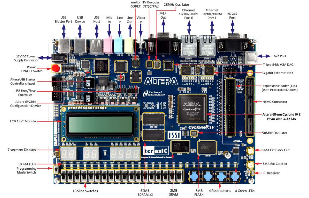
Interfaces
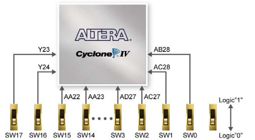
Ligação e pinagem das Chaves SW01-17
Pinagem das chaves SW01-17 - DE2-115
| Signal Name | FPGA Pin No. | Pin | I/O Standard |
|---|---|---|---|
| SW[0] | PIN_AB28 | Slide Switch[0] | Depending on JP7 |
| SW[1] | PIN_AC28 | Slide Switch[1] | Depending on JP7 |
| SW[2] | PIN_AC27 | Slide Switch[2] | Depending on JP7 |
| SW[3] | PIN_AD27 | Slide Switch[3] | Depending on JP7 |
| SW[4] | PIN_AB27 | Slide Switch[4] | Depending on JP7 |
| SW[5] | PIN_AC26 | Slide Switch[5] | Depending on JP7 |
| SW[6] | PIN_AD26 | Slide Switch[6] | Depending on JP7 |
| SW[7] | PIN_AB26 | Slide Switch[7] | Depending on JP7 |
| SW[8] | PIN_AC25 | Slide Switch[8] | Depending on JP7 |
| SW[9] | PIN_AB25 | Slide Switch[9] | Depending on JP7 |
| SW[10] | PIN_AC24 | Slide Switch[10] | Depending on JP7 |
| SW[11] | PIN_AB24 | Slide Switch[11] | Depending on JP7 |
| SW[12] | PIN_AB23 | Slide Switch[12] | Depending on JP7 |
| SW[13] | PIN_AA24 | Slide Switch[13] | Depending on JP7 |
| SW[14] | PIN_AA23 | Slide Switch[14] | Depending on JP7 |
| SW[15] | PIN_AA22 | Slide Switch[15] | Depending on JP7 |
| SW[16] | PIN_Y24 | Slide Switch[16] | Depending on JP7 |
| SW[17] | PIN_Y23 | Slide Switch[17] | Depending on JP7 |
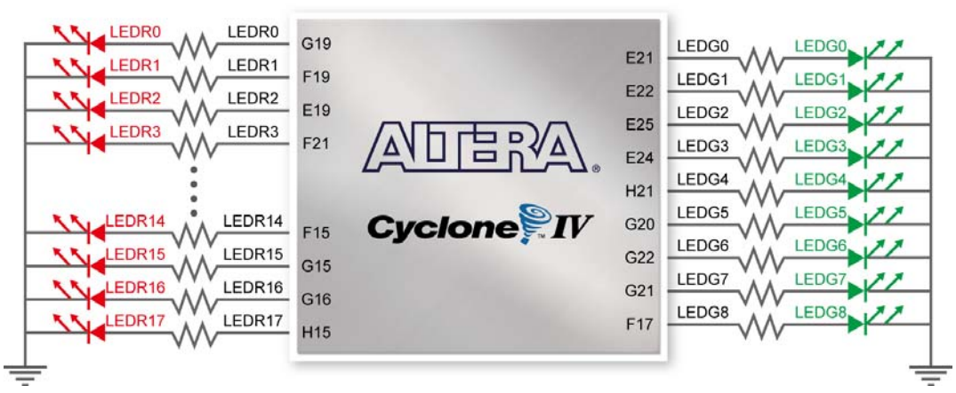
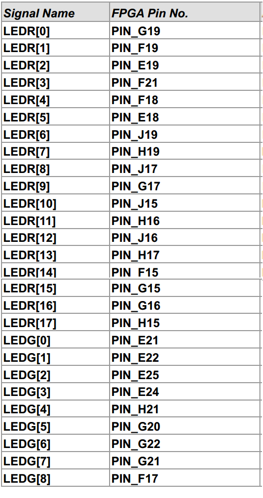
Ligação e pinagem dos Leds
Ligação e pinagem dos Displays
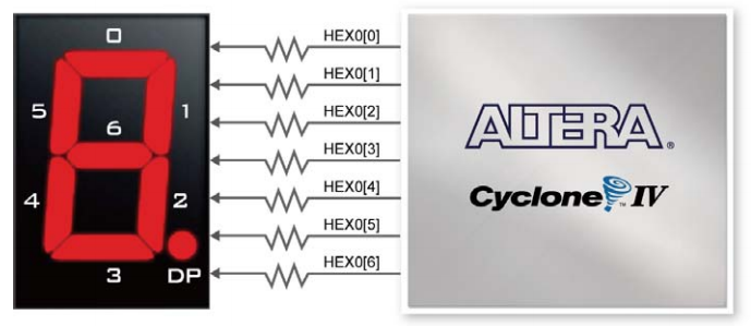
A placa DE2-115 tem oito Display de 7 segmentos. Estes displays são do tipo anodo comum. Eles estão conectados aos pinos do FPGA Cyclone IV conforme mostrado na figura abaixo. A pinagem no FPGA é mostrado na tabela abaixo. Aplicando um nível lógico '0' no pino correspondente fará com que o segmento acenda, enquanto que a aplicação do nível lógico '1' fará com com que ele fique apagado. Cada segmento é identificado com um índice de 0, 1, 2, 3, 4, 5, 6 (que correspondem os segmentos a, b, c, d, e, f, g).
Pinagem dos oito Display de sete segmentos
| Segment | Signal Name | FPGA Pin No. | I/O Standard |
|---|---|---|---|
| a | HEX0[0] | PIN_G18 | 2.5V |
| b | HEX0[1] | PIN_F22 | 2.5V |
| c | HEX0[2] | PIN_E17 | 2.5V |
| d | HEX0[3] | PIN_L26 | Depending on JP7 |
| e | HEX0[4] | PIN_L25 | Depending on JP7 |
| f | HEX0[5] | PIN_J22 | Depending on JP7 |
| g | HEX0[6] | PIN_H22 | Depending on JP7 |
| a | HEX1[0] | PIN_M24 | Depending on JP7 |
| b | HEX1[1] | PIN_Y22 | Depending on JP7 |
| c | HEX1[2] | PIN_W21 | Depending on JP7 |
| d | HEX1[3] | PIN_W22 | Depending on JP7 |
| e | HEX1[4] | PIN_W25 | Depending on JP7 |
| f | HEX1[5] | PIN_U23 | Depending on JP7 |
| g | HEX1[6] | PIN_U24 | Depending on JP7 |
| a | HEX2[0] | PIN_AA25 | Depending on JP7 |
| b | HEX2[1] | PIN_AA26 | Depending on JP7 |
| c | HEX2[2] | PIN_Y25 | Depending on JP7 |
| d | HEX2[3] | PIN_W26 | Depending on JP7 |
| e | HEX2[4] | PIN_Y26 | Depending on JP7 |
| f | HEX2[5] | PIN_W27 | Depending on JP7 |
| g | HEX2[6] | PIN_W28 | Depending on JP7 |
| a | HEX3[0] | PIN_V21 | Depending on JP7 |
| b | HEX3[1] | PIN_U21 | Depending on JP7 |
| c | HEX3[2] | PIN_AB20 | Depending on JP6 |
| d | HEX3[3] | PIN_AA21 | Depending on JP6 |
| e | HEX3[4] | PIN_AD24 | Depending on JP6 |
| f | HEX3[5] | PIN_AF23 | Depending on JP6 |
| g | HEX3[6] | PIN_Y19 | Depending on JP6 |
| a | HEX4[0] | PIN_AB19 | Depending on JP6 |
| b | HEX4[1] | PIN_AA19 | Depending on JP6 |
| c | HEX4[2] | PIN_AG21 | Depending on JP6 |
| d | HEX4[3] | PIN_AH21 | Depending on JP6 |
| e | HEX4[4] | PIN_AE19 | Depending on JP6 |
| f | HEX4[5] | PIN_AF19 | Depending on JP6 |
| g | HEX4[6] | PIN_AE18 | Depending on JP6 |
| a | HEX5[0] | PIN_AD18 | Depending on JP6 |
| b | HEX5[1] | PIN_AC18 | Depending on JP6 |
| c | HEX5[2] | PIN_AB18 | Depending on JP6 |
| d | HEX5[3] | PIN_AH19 | Depending on JP6 |
| e | HEX5[4] | PIN_AG19 | Depending on JP6 |
| f | HEX5[5] | PIN_AF18 | Depending on JP6 |
| g | HEX5[6] | PIN_AH18 | Depending on JP6 |
| a | HEX6[0] | PIN_AA17 | Depending on JP6 |
| b | HEX6[1] | PIN_AB16 | Depending on JP6 |
| c | HEX6[2] | PIN_AA16 | Depending on JP6 |
| d | HEX6[3] | PIN_AB17 | Depending on JP6 |
| e | HEX6[4] | PIN_AB15 | Depending on JP6 |
| f | HEX6[5] | PIN_AA15 | Depending on JP6 |
| g | HEX6[6] | PIN_AC17 | Depending on JP6 |
| a | HEX7[0] | PIN_AD17 | Depending on JP6 |
| b | HEX7[1] | PIN_AE17 | Depending on JP6 |
| c | HEX7[2] | PIN_AG17 | Depending on JP6 |
| d | HEX7[3] | PIN_AH17 | Depending on JP6 |
| e | HEX7[4] | PIN_AF17 | Depending on JP6 |
| f | HEX7[5] | PIN_AG18 | Depending on JP6 |
| g | HEX7[6] | PIN_AA14 | 3.3V |
