Mudanças entre as edições de "Interfaces de entrada e saída da DE2-115"
| (24 revisões intermediárias por 2 usuários não estão sendo mostradas) | |||
| Linha 1: | Linha 1: | ||
| − | =Interfaces= | + | =Interfaces Externas= |
| + | <span style="font-size:200%"> Family=Cyclone IV, device=EP4CE115F29C7 </span> | ||
| + | |||
<center> | <center> | ||
[[Arquivo:InterfacesDE2-115.png]] | [[Arquivo:InterfacesDE2-115.png]] | ||
</center> | </center> | ||
| − | = | + | =Conexões do Sinal de Clock= |
| − | < | + | [[Arquivo:ConectDE2-115-Clock50MHz.png | right | 400px]] |
| − | [[Arquivo:ConectDE2-115- | + | <table border="1" cellpadding="2"> |
| − | </center> | + | <tr><th> Signal <th> Name FPGA <th> Pin No. Description <th> I/O Standard |
| + | <tr><td> CLOCK_50 <td> PIN_Y2 <td> 50 MHz clock input <td> 3.3V | ||
| + | <tr><td> CLOCK2_50 <td> PIN_AG14 <td> 50 MHz clock input <td> 3.3V | ||
| + | <tr><td> CLOCK3_50 <td> PIN_AG15 <td> 50 MHz clock input <td> Depending on JP6 | ||
| + | <tr><td> SMA_CLKOUT <td> PIN_AE23 <td> External (SMA) clock output <td> Depending on JP6 | ||
| + | <tr><td> SMA_CLKIN <td> PIN_AH14 <td> External (SMA) clock input <td> 3.3V | ||
| + | </table> | ||
| + | |||
| + | =Conexões das Chaves de contato momentâneo KEY0-3= | ||
| + | |||
| + | Observe atentamente este diagrama, pois as chaves pushbottom estão normalmente em '''HIGH''', e enquanto estiverem acionadas mudam para '''LOW'''. Muita atenção especialmente se for usar essa chave para um '''RESET''' do sistema. Neste caso normalmente é necessário incluir um inversor no circuito. | ||
| + | |||
| + | [[Arquivo:ConectDE2-115-KEY0-3.png | right |400px]] | ||
| + | <br> | ||
| + | |||
| + | <table border="1" cellpadding="2"> | ||
| + | <tr><th> Signal <th> Name FPGA <th> Pin No. Description <th> I/O Standard | ||
| + | <tr><td> KEY[0] <td> PIN_M23 <td> Push-button[0] <td> Depending on JP7 | ||
| + | <tr><td> KEY[1] <td> PIN_M21 <td> Push-button[1] <td> Depending on JP7 | ||
| + | <tr><td> KEY[2] <td> PIN_N21 <td> Push-button[2] <td> Depending on JP7 | ||
| + | <tr><td> KEY[3] <td> PIN_R24 <td> Push-button[3] <td> Depending on JP7 | ||
| + | </table> | ||
| + | |||
| + | =Conexões das Chaves SW01-17= | ||
| + | [[Arquivo:ConectDE2-115-SW1a17.png | right |400px]] | ||
| + | <table border="1" cellpadding="2"> | ||
| + | <tr><th> Signal Name <th> FPGA Pin No. <th> Pin <th> I/O Standard | ||
| + | <tr><td> SW[0] <td> PIN_AB28 <td> Slide Switch[0] <td> Depending on JP7 | ||
| + | <tr><td> SW[1] <td> PIN_AC28 <td> Slide Switch[1] <td> Depending on JP7 | ||
| + | <tr><td> SW[2] <td> PIN_AC27 <td> Slide Switch[2] <td> Depending on JP7 | ||
| + | <tr><td> SW[3] <td> PIN_AD27 <td> Slide Switch[3] <td> Depending on JP7 | ||
| + | <tr><td> SW[4] <td> PIN_AB27 <td> Slide Switch[4] <td> Depending on JP7 | ||
| + | <tr><td> SW[5] <td> PIN_AC26 <td> Slide Switch[5] <td> Depending on JP7 | ||
| + | <tr><td> SW[6] <td> PIN_AD26 <td> Slide Switch[6] <td> Depending on JP7 | ||
| + | <tr><td> SW[7] <td> PIN_AB26 <td> Slide Switch[7] <td> Depending on JP7 | ||
| + | <tr><td> SW[8] <td> PIN_AC25 <td> Slide Switch[8] <td> Depending on JP7 | ||
| + | <tr><td> SW[9] <td> PIN_AB25 <td> Slide Switch[9] <td> Depending on JP7 | ||
| + | <tr><td> SW[10] <td> PIN_AC24 <td> Slide Switch[10] <td> Depending on JP7 | ||
| + | <tr><td> SW[11] <td> PIN_AB24 <td> Slide Switch[11] <td> Depending on JP7 | ||
| + | <tr><td> SW[12] <td> PIN_AB23 <td> Slide Switch[12] <td> Depending on JP7 | ||
| + | <tr><td> SW[13] <td> PIN_AA24 <td> Slide Switch[13] <td> Depending on JP7 | ||
| + | <tr><td> SW[14] <td> PIN_AA23 <td> Slide Switch[14] <td> Depending on JP7 | ||
| + | <tr><td> SW[15] <td> PIN_AA22 <td> Slide Switch[15] <td> Depending on JP7 | ||
| + | <tr><td> SW[16] <td> PIN_Y24 <td> Slide Switch[16] <td> Depending on JP7 | ||
| + | <tr><td> SW[17] <td> PIN_Y23 <td> Slide Switch[17] <td> Depending on JP7 | ||
| + | </table> | ||
| + | |||
| + | =Conexões dos Leds= | ||
| + | [[Arquivo:ConectDE2-115-LEDR.png | right |400px]] | ||
| + | |||
| + | ==Pinagem dos LEDs verdes LEDG0-8== | ||
| + | |||
| + | <table border="1" cellpadding="2"> | ||
| + | <tr><th> Signal <th> Name FPGA <th> Pin No. Description <th> I/O Standard | ||
| + | <tr><td> LEDG[0] <td> PIN_E21 <td> LED Green[0] <td> 2.5V | ||
| + | <tr><td> LEDG[1] <td> PIN_E22 <td> LED Green[1] <td> 2.5V | ||
| + | <tr><td> LEDG[2] <td> PIN_E25 <td> LED Green[2] <td> 2.5V | ||
| + | <tr><td> LEDG[3] <td> PIN_E24 <td> LED Green[3] <td> 2.5V | ||
| + | <tr><td> LEDG[4] <td> PIN_H21 <td> LED Green[4] <td> 2.5V | ||
| + | <tr><td> LEDG[5] <td> PIN_G20 <td> LED Green[5] <td> 2.5V | ||
| + | <tr><td> LEDG[6] <td> PIN_G22 <td> LED Green[6] <td> 2.5V | ||
| + | <tr><td> LEDG[7] <td> PIN_G21 <td> LED Green[7] <td> 2.5V | ||
| + | <tr><td> LEDG[8] <td> PIN_F17 <td> LED Green[8] <td> 2.5V | ||
| + | </table> | ||
| + | |||
| + | ==Pinagem dos LEDs vermelhos LEDR0-17== | ||
| + | <table border="1" cellpadding="2"> | ||
| + | <tr><th> Signal <th> Name FPGA <th> Pin No. Description <th> I/O Standard | ||
| + | <tr><td> LEDR[0] <td> PIN_G19 <td> LED Red[0] <td> 2.5V | ||
| + | <tr><td> LEDR[1] <td> PIN_F19 <td> LED Red[1] <td> 2.5V | ||
| + | <tr><td> LEDR[2] <td> PIN_E19 <td> LED Red[2] <td> 2.5V | ||
| + | <tr><td> LEDR[3] <td> PIN_F21 <td> LED Red[3] <td> 2.5V | ||
| + | <tr><td> LEDR[4] <td> PIN_F18 <td> LED Red[4] <td> 2.5V | ||
| + | <tr><td> LEDR[5] <td> PIN_E18 <td> LED Red[5] <td> 2.5V | ||
| + | <tr><td> LEDR[6] <td> PIN_J19 <td> LED Red[6] <td> 2.5V | ||
| + | <tr><td> LEDR[7] <td> PIN_H19 <td> LED Red[7] <td> 2.5V | ||
| + | <tr><td> LEDR[8] <td> PIN_J17 <td> LED Red[8] <td> 2.5V | ||
| + | <tr><td> LEDR[9] <td> PIN_G17 <td> LED Red[9] <td> 2.5V | ||
| + | <tr><td> LEDR[10] <td> PIN_J15 <td> LED Red[10] <td> 2.5V | ||
| + | <tr><td> LEDR[11] <td> PIN_H16 <td> LED Red[11] <td> 2.5V | ||
| + | <tr><td> LEDR[12] <td> PIN_J16 <td> LED Red[12] <td> 2.5V | ||
| + | <tr><td> LEDR[13] <td> PIN_H17 <td> LED Red[13] <td> 2.5V | ||
| + | <tr><td> LEDR[14] <td> PIN_F15 <td> LED Red[14] <td> 2.5V | ||
| + | <tr><td> LEDR[15] <td> PIN_G15 <td> LED Red[15] <td> 2.5V | ||
| + | <tr><td> LEDR[16] <td> PIN_G16 <td> LED Red[16] <td> 2.5V | ||
| + | <tr><td> LEDR[17] <td> PIN_H15 <td> LED Red[17] <td> 2.5V | ||
| + | </table> | ||
| + | |||
| + | =Conexão dos Displays= | ||
| + | A placa DE2-115 tem oito [[Display de 7 segmentos]]. Estes displays são do tipo [[Display de 7 segmentos#Anodo_comum | '''anodo comum''']]. Eles estão conectados aos pinos do FPGA Cyclone IV conforme mostrado na figura abaixo. A pinagem no FPGA é mostrado na tabela abaixo. | ||
| + | Aplicando um nível lógico '0' no pino correspondente fará com que o segmento acenda, enquanto que a aplicação do nível lógico '1' fará com com que ele fique apagado. Cada segmento é identificado com um índice de 0, 1, 2, 3, 4, 5, 6 (que correspondem os segmentos a, b, c, d, e, f, g). O LED do ponto decimal (DP) dos displays não está conectado ao FPGA. | ||
| + | |||
| + | [[Arquivo:ConectDE2-115-Display.png | right |400px]] | ||
| + | |||
| + | ==Pinagem dos oito Display de sete segmentos== | ||
| + | [[Arquivo:DE2-115-Display.png | right |400px]] | ||
| + | |||
| + | <table border="1" cellpadding="2"> | ||
| + | <tr><th> Segment <th> Signal Name <th> FPGA Pin No. <th> I/O Standard | ||
| + | <tr><td> a <td> HEX0[0] <td> PIN_G18 <td> 2.5V | ||
| + | <tr><td> b <td> HEX0[1] <td> PIN_F22 <td> 2.5V | ||
| + | <tr><td> c <td> HEX0[2] <td> PIN_E17 <td> 2.5V | ||
| + | <tr><td> d <td> HEX0[3] <td> PIN_L26 <td> Depending on JP7 | ||
| + | <tr><td> e <td> HEX0[4] <td> PIN_L25 <td> Depending on JP7 | ||
| + | <tr><td> f <td> HEX0[5] <td> PIN_J22 <td> Depending on JP7 | ||
| + | <tr><td> g <td> HEX0[6] <td> PIN_H22 <td> Depending on JP7 | ||
| + | <tr><th> Segment <th> Signal Name <th> FPGA Pin No. <th> I/O Standard | ||
| + | <tr><td> a <td> HEX1[0] <td> PIN_M24 <td> Depending on JP7 | ||
| + | <tr><td> b <td> HEX1[1] <td> PIN_Y22 <td> Depending on JP7 | ||
| + | <tr><td> c <td> HEX1[2] <td> PIN_W21 <td> Depending on JP7 | ||
| + | <tr><td> d <td> HEX1[3] <td> PIN_W22 <td> Depending on JP7 | ||
| + | <tr><td> e <td> HEX1[4] <td> PIN_W25 <td> Depending on JP7 | ||
| + | <tr><td> f <td> HEX1[5] <td> PIN_U23 <td> Depending on JP7 | ||
| + | <tr><td> g <td> HEX1[6] <td> PIN_U24 <td> Depending on JP7 | ||
| + | <tr><th> Segment <th> Signal Name <th> FPGA Pin No. <th> I/O Standard | ||
| + | <tr><td> a <td> HEX2[0] <td> PIN_AA25 <td> Depending on JP7 | ||
| + | <tr><td> b <td> HEX2[1] <td> PIN_AA26 <td> Depending on JP7 | ||
| + | <tr><td> c <td> HEX2[2] <td> PIN_Y25 <td> Depending on JP7 | ||
| + | <tr><td> d <td> HEX2[3] <td> PIN_W26 <td> Depending on JP7 | ||
| + | <tr><td> e <td> HEX2[4] <td> PIN_Y26 <td> Depending on JP7 | ||
| + | <tr><td> f <td> HEX2[5] <td> PIN_W27 <td> Depending on JP7 | ||
| + | <tr><td> g <td> HEX2[6] <td> PIN_W28 <td> Depending on JP7 | ||
| + | <tr><th> Segment <th> Signal Name <th> FPGA Pin No. <th> I/O Standard | ||
| + | <tr><td> a <td> HEX3[0] <td> PIN_V21 <td> Depending on JP7 | ||
| + | <tr><td> b <td> HEX3[1] <td> PIN_U21 <td> Depending on JP7 | ||
| + | <tr><td> c <td> HEX3[2] <td> PIN_AB20 <td> Depending on JP6 | ||
| + | <tr><td> d <td> HEX3[3] <td> PIN_AA21 <td> Depending on JP6 | ||
| + | <tr><td> e <td> HEX3[4] <td> PIN_AD24 <td> Depending on JP6 | ||
| + | <tr><td> f <td> HEX3[5] <td> PIN_AF23 <td> Depending on JP6 | ||
| + | <tr><td> g <td> HEX3[6] <td> PIN_Y19 <td> Depending on JP6 | ||
| + | <tr><th> Segment <th> Signal Name <th> FPGA Pin No. <th> I/O Standard | ||
| + | <tr><td> a <td> HEX4[0] <td> PIN_AB19 <td> Depending on JP6 | ||
| + | <tr><td> b <td> HEX4[1] <td> PIN_AA19 <td> Depending on JP6 | ||
| + | <tr><td> c <td> HEX4[2] <td> PIN_AG21 <td> Depending on JP6 | ||
| + | <tr><td> d <td> HEX4[3] <td> PIN_AH21 <td> Depending on JP6 | ||
| + | <tr><td> e <td> HEX4[4] <td> PIN_AE19 <td> Depending on JP6 | ||
| + | <tr><td> f <td> HEX4[5] <td> PIN_AF19 <td> Depending on JP6 | ||
| + | <tr><td> g <td> HEX4[6] <td> PIN_AE18 <td> Depending on JP6 | ||
| + | <tr><th> Segment <th> Signal Name <th> FPGA Pin No. <th> I/O Standard | ||
| + | <tr><td> a <td> HEX5[0] <td> PIN_AD18 <td> Depending on JP6 | ||
| + | <tr><td> b <td> HEX5[1] <td> PIN_AC18 <td> Depending on JP6 | ||
| + | <tr><td> c <td> HEX5[2] <td> PIN_AB18 <td> Depending on JP6 | ||
| + | <tr><td> d <td> HEX5[3] <td> PIN_AH19 <td> Depending on JP6 | ||
| + | <tr><td> e <td> HEX5[4] <td> PIN_AG19 <td> Depending on JP6 | ||
| + | <tr><td> f <td> HEX5[5] <td> PIN_AF18 <td> Depending on JP6 | ||
| + | <tr><td> g <td> HEX5[6] <td> PIN_AH18 <td> Depending on JP6 | ||
| + | <tr><th> Segment <th> Signal Name <th> FPGA Pin No. <th> I/O Standard | ||
| + | <tr><td> a <td> HEX6[0] <td> PIN_AA17 <td> Depending on JP6 | ||
| + | <tr><td> b <td> HEX6[1] <td> PIN_AB16 <td> Depending on JP6 | ||
| + | <tr><td> c <td> HEX6[2] <td> PIN_AA16 <td> Depending on JP6 | ||
| + | <tr><td> d <td> HEX6[3] <td> PIN_AB17 <td> Depending on JP6 | ||
| + | <tr><td> e <td> HEX6[4] <td> PIN_AB15 <td> Depending on JP6 | ||
| + | <tr><td> f <td> HEX6[5] <td> PIN_AA15 <td> Depending on JP6 | ||
| + | <tr><td> g <td> HEX6[6] <td> PIN_AC17 <td> Depending on JP6 | ||
| + | <tr><th> Segment <th> Signal Name <th> FPGA Pin No. <th> I/O Standard | ||
| + | <tr><td> a <td> HEX7[0] <td> PIN_AD17 <td> Depending on JP6 | ||
| + | <tr><td> b <td> HEX7[1] <td> PIN_AE17 <td> Depending on JP6 | ||
| + | <tr><td> c <td> HEX7[2] <td> PIN_AG17 <td> Depending on JP6 | ||
| + | <tr><td> d <td> HEX7[3] <td> PIN_AH17 <td> Depending on JP6 | ||
| + | <tr><td> e <td> HEX7[4] <td> PIN_AF17 <td> Depending on JP6 | ||
| + | <tr><td> f <td> HEX7[5] <td> PIN_AG18 <td> Depending on JP6 | ||
| + | <tr><td> g <td> HEX7[6] <td> PIN_AA14 <td> 3.3V | ||
| + | </table> | ||
| + | |||
| + | =Conexão do LCD= | ||
| + | A placa DE2-115 tem um [[LCD de 2 x 16 caracteres]]. Ele está conectados aos pinos do FPGA Cyclone IV conforme mostrado na figura abaixo. A pinagem no FPGA é mostrado na tabela abaixo. | ||
| + | |||
| + | O módulo LCD tem um gerador de caracteres que pode ser utilizado para mostrar os textos a partir do envio de comandos adequados para o controlador de display. Informações detalhadas sobre o uso do controlador podem ser obtidas no datasheet do [[Media:HD44780.pdf | HD44780]]. | ||
| + | [[Arquivo:ConectDE2-115-LCD.png | right |300px]] | ||
| + | |||
| + | ==Pinagem LCD== | ||
| + | <table border="1" cellpadding="2"> | ||
| + | <tr><th> Signal Name <th> FPGA Pin No. <th> I/O Standard | ||
| + | <tr><td> LCD_DATA[7] <td> PIN_M5 <td> 3.3V | ||
| + | <tr><td> LCD_DATA[6] <td> PIN_M3 <td> 3.3V | ||
| + | <tr><td> LCD_DATA[5] <td> PIN_K2 <td> 3.3V | ||
| + | <tr><td> LCD_DATA[4] <td> PIN_K1 <td> 3.3V | ||
| + | <tr><td> LCD_DATA[3] <td> PIN_K7 <td> 3.3V | ||
| + | <tr><td> LCD_DATA[2] <td> PIN_L2 <td> 3.3V | ||
| + | <tr><td> LCD_DATA[1] <td> PIN_L1 <td> 3.3V | ||
| + | <tr><td> LCD_DATA[0] <td> PIN_L3 <td> 3.3V | ||
| + | <tr><td> LCD Enable <td> PIN_L4 <td> 3.3V | ||
| + | <tr><td> LCD Read/~Write <td> PIN_M1 <td> 3.3V | ||
| + | <tr><td> LCD LCD Data Select/~Command <td> PIN_M2 <td> 3.3V | ||
| + | <tr><td> LCD Power ON <td> PIN_L5 <td> 3.3V | ||
| + | <tr><td> LCD Back Light ON <td> PIN_L6 <td> 3.3V | ||
| + | </table> | ||
| + | |||
| + | =Conector GPIO= | ||
| + | A placa DE2-115 tem um conector (JP5) que tem pinos de entrada e saída propósito geral (General-Purpose Input/Output - GPIO) de 40 pinos que pode ser utilizada para conexão de circuitos externos. A pinagem no FPGA é mostrado na figura abaixo. | ||
| + | |||
| + | <center>[[Arquivo:GPIO_DE2-115.png | 800px]]</center> | ||
| + | |||
| + | |||
| + | ;Detalhes importantes: | ||
| + | *Cada um dos pinos do conector está ligado a um pinos do FPGA Cyclone IV conforme indicado pelo número de pino em azul na figura acima. | ||
| + | *Os pinos 12 e 30 estão ligados ao GND da placa, o pino 11 está ligado ao 5V e o pino 29 ao 3.3V. | ||
| + | *Todos os demais pinos estão conectados ao FPGA através de um resistor de 47 ohms e com dois diodos zener de proteção conforme mostra a figura abaixo. | ||
| + | |||
| + | <center> [[Arquivo:GPIO_saida_DE2-115.png | 600px]] </center> | ||
| − | + | *A potência máxima que pode ser consumida dos pinos de alimentação é de 1A em 5V e 1.5A em 3.3V. | |
| − | + | *O nivel de tensão os pinos da GPIO pode ser ajustada para 3.3V (default), 2.5V, 1.8V, ou 1.5V usando o ''jumper'' JP6. Infelizmente o ''jumper'' está sob o acrílico e não pode ser facilmente mudado. | |
| − | + | ==Pinagem da GPIO== | |
| − | = | + | {| class="wikitable sortable" border="1" cellpadding="3" cellspacing="0" style="text-align:center; font-size:100%" bgcolor="#efefef" |
| − | + | ! scope="col" width=30% align="center" | Nr do pino no conector | |
| − | [[ | + | ! scope="col" width=40% align="center"| Nome do sinal |
| − | + | ! scope="col" width=30% align="center" | Nr do pino no FPGA | |
| + | |- | ||
| + | | 1 || GPIO[0] || PIN_AB22 | ||
| + | |- | ||
| + | | 2 || GPIO[1] || PIN_AC15 | ||
| + | |- | ||
| + | | 3 || GPIO[2] || PIN_AB21 | ||
| + | |- | ||
| + | | 4 || GPIO[3] || PIN_Y17 | ||
| + | |- | ||
| + | | 5 || GPIO[4] || PIN_AC21 | ||
| + | |- | ||
| + | | 6 || GPIO[5] || PIN_Y16 | ||
| + | |- | ||
| + | | 7 || GPIO[6] || PIN_AD21 | ||
| + | |- | ||
| + | | 8 || GPIO[7] || PIN_AE16 | ||
| + | |- | ||
| + | | 9 || GPIO[8] || PIN_AD15 | ||
| + | |- | ||
| + | | 10 || GPIO[9] || PIN_AE15 | ||
| + | |- | ||
| + | | 11 || 5V || NC | ||
| + | |- | ||
| + | | 12 || GND || NC | ||
| + | |- | ||
| + | | 13 || GPIO[10] || PIN_AC19 | ||
| + | |- | ||
| + | | 14 || GPIO[11] || PIN_AF16 | ||
| + | |- | ||
| + | | 15 || GPIO[12] || PIN_AD19 | ||
| + | |- | ||
| + | | 16 || GPIO[13] || PIN_AF15 | ||
| + | |- | ||
| + | | 17 || GPIO[14] || PIN_AF24 | ||
| + | |- | ||
| + | | 18 || GPIO[15] || PIN_AE21 | ||
| + | |- | ||
| + | | 19 || GPIO[16] || PIN_AF25 | ||
| + | |- | ||
| + | | 20 || GPIO[17] || PIN_AC22 | ||
| + | |- | ||
| + | | 21 || GPIO[18] || PIN_AE22 | ||
| + | |- | ||
| + | | 22 || GPIO[19] || PIN_AF21 | ||
| + | |- | ||
| + | | 23 || GPIO[20] || PIN_AF22 | ||
| + | |- | ||
| + | | 24 || GPIO[21] || PIN_AD22 | ||
| + | |- | ||
| + | | 25 || GPIO[22] || PIN_AG25 | ||
| + | |- | ||
| + | | 26 || GPIO[23] || PIN_AD25 | ||
| + | |- | ||
| + | | 27 || GPIO[24] || PIN_AH25 | ||
| + | |- | ||
| + | | 28 || GPIO[25] || PIN_AE25 | ||
| + | |- | ||
| + | | 29 || 3.3V || NC | ||
| + | |- | ||
| + | | 30 || GND || NC | ||
| + | |- | ||
| + | | 31 || GPIO[26] || PIN_AG22 | ||
| + | |- | ||
| + | | 32 || GPIO[27] || PIN_AE24 | ||
| + | |- | ||
| + | | 33 || GPIO[28] || PIN_AH22 | ||
| + | |- | ||
| + | | 34 || GPIO[29] || PIN_AF26 | ||
| + | |- | ||
| + | | 35 || GPIO[30] || PIN_AE20 | ||
| + | |- | ||
| + | | 36 || GPIO[31] || PIN_AG23 | ||
| + | |- | ||
| + | | 37 || GPIO[32] || PIN_AF20 | ||
| + | |- | ||
| + | | 38 || GPIO[33] || PIN_AH26 | ||
| + | |- | ||
| + | | 39 || GPIO[34] || PIN_AH23 | ||
| + | |- | ||
| + | | 40 || GPIO[35] || PIN_AG26 | ||
| + | |- | ||
| + | |} | ||
| − | + | [[Categoria:FPGA]] | |
| − | [[ | ||
| − | |||
Edição atual tal como às 13h14min de 23 de junho de 2022
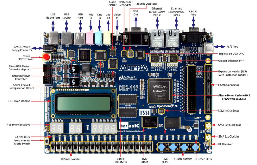
Interfaces Externas
Family=Cyclone IV, device=EP4CE115F29C7
Conexões do Sinal de Clock
| Signal | Name FPGA | Pin No. Description | I/O Standard |
|---|---|---|---|
| CLOCK_50 | PIN_Y2 | 50 MHz clock input | 3.3V |
| CLOCK2_50 | PIN_AG14 | 50 MHz clock input | 3.3V |
| CLOCK3_50 | PIN_AG15 | 50 MHz clock input | Depending on JP6 |
| SMA_CLKOUT | PIN_AE23 | External (SMA) clock output | Depending on JP6 |
| SMA_CLKIN | PIN_AH14 | External (SMA) clock input | 3.3V |
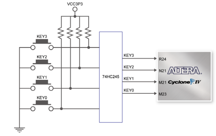
Conexões das Chaves de contato momentâneo KEY0-3
Observe atentamente este diagrama, pois as chaves pushbottom estão normalmente em HIGH, e enquanto estiverem acionadas mudam para LOW. Muita atenção especialmente se for usar essa chave para um RESET do sistema. Neste caso normalmente é necessário incluir um inversor no circuito.
| Signal | Name FPGA | Pin No. Description | I/O Standard |
|---|---|---|---|
| KEY[0] | PIN_M23 | Push-button[0] | Depending on JP7 |
| KEY[1] | PIN_M21 | Push-button[1] | Depending on JP7 |
| KEY[2] | PIN_N21 | Push-button[2] | Depending on JP7 |
| KEY[3] | PIN_R24 | Push-button[3] | Depending on JP7 |
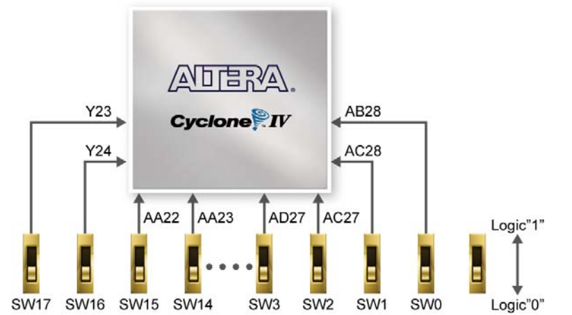
Conexões das Chaves SW01-17
| Signal Name | FPGA Pin No. | Pin | I/O Standard |
|---|---|---|---|
| SW[0] | PIN_AB28 | Slide Switch[0] | Depending on JP7 |
| SW[1] | PIN_AC28 | Slide Switch[1] | Depending on JP7 |
| SW[2] | PIN_AC27 | Slide Switch[2] | Depending on JP7 |
| SW[3] | PIN_AD27 | Slide Switch[3] | Depending on JP7 |
| SW[4] | PIN_AB27 | Slide Switch[4] | Depending on JP7 |
| SW[5] | PIN_AC26 | Slide Switch[5] | Depending on JP7 |
| SW[6] | PIN_AD26 | Slide Switch[6] | Depending on JP7 |
| SW[7] | PIN_AB26 | Slide Switch[7] | Depending on JP7 |
| SW[8] | PIN_AC25 | Slide Switch[8] | Depending on JP7 |
| SW[9] | PIN_AB25 | Slide Switch[9] | Depending on JP7 |
| SW[10] | PIN_AC24 | Slide Switch[10] | Depending on JP7 |
| SW[11] | PIN_AB24 | Slide Switch[11] | Depending on JP7 |
| SW[12] | PIN_AB23 | Slide Switch[12] | Depending on JP7 |
| SW[13] | PIN_AA24 | Slide Switch[13] | Depending on JP7 |
| SW[14] | PIN_AA23 | Slide Switch[14] | Depending on JP7 |
| SW[15] | PIN_AA22 | Slide Switch[15] | Depending on JP7 |
| SW[16] | PIN_Y24 | Slide Switch[16] | Depending on JP7 |
| SW[17] | PIN_Y23 | Slide Switch[17] | Depending on JP7 |
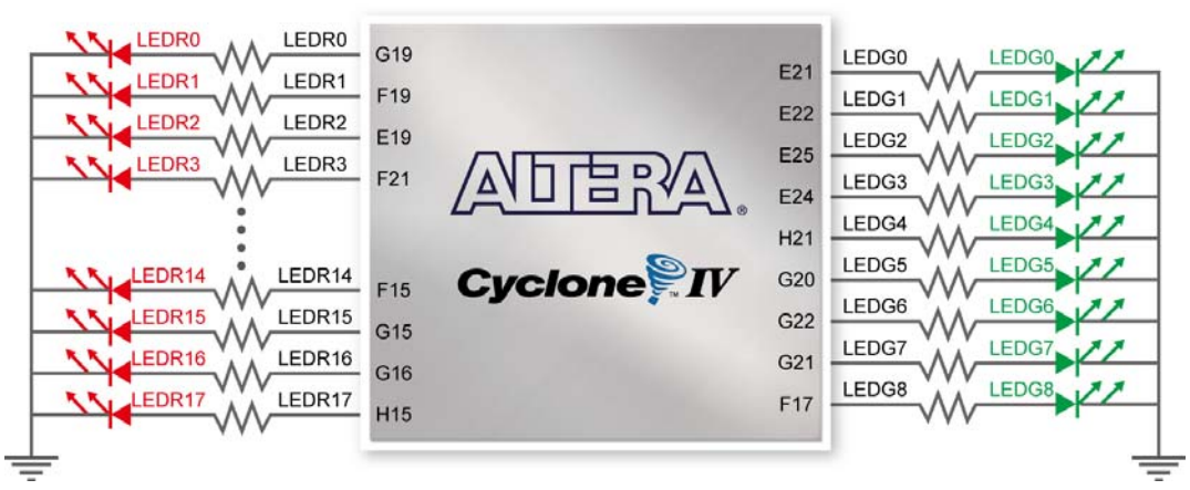
Conexões dos Leds
Pinagem dos LEDs verdes LEDG0-8
| Signal | Name FPGA | Pin No. Description | I/O Standard |
|---|---|---|---|
| LEDG[0] | PIN_E21 | LED Green[0] | 2.5V |
| LEDG[1] | PIN_E22 | LED Green[1] | 2.5V |
| LEDG[2] | PIN_E25 | LED Green[2] | 2.5V |
| LEDG[3] | PIN_E24 | LED Green[3] | 2.5V |
| LEDG[4] | PIN_H21 | LED Green[4] | 2.5V |
| LEDG[5] | PIN_G20 | LED Green[5] | 2.5V |
| LEDG[6] | PIN_G22 | LED Green[6] | 2.5V |
| LEDG[7] | PIN_G21 | LED Green[7] | 2.5V |
| LEDG[8] | PIN_F17 | LED Green[8] | 2.5V |
Pinagem dos LEDs vermelhos LEDR0-17
| Signal | Name FPGA | Pin No. Description | I/O Standard |
|---|---|---|---|
| LEDR[0] | PIN_G19 | LED Red[0] | 2.5V |
| LEDR[1] | PIN_F19 | LED Red[1] | 2.5V |
| LEDR[2] | PIN_E19 | LED Red[2] | 2.5V |
| LEDR[3] | PIN_F21 | LED Red[3] | 2.5V |
| LEDR[4] | PIN_F18 | LED Red[4] | 2.5V |
| LEDR[5] | PIN_E18 | LED Red[5] | 2.5V |
| LEDR[6] | PIN_J19 | LED Red[6] | 2.5V |
| LEDR[7] | PIN_H19 | LED Red[7] | 2.5V |
| LEDR[8] | PIN_J17 | LED Red[8] | 2.5V |
| LEDR[9] | PIN_G17 | LED Red[9] | 2.5V |
| LEDR[10] | PIN_J15 | LED Red[10] | 2.5V |
| LEDR[11] | PIN_H16 | LED Red[11] | 2.5V |
| LEDR[12] | PIN_J16 | LED Red[12] | 2.5V |
| LEDR[13] | PIN_H17 | LED Red[13] | 2.5V |
| LEDR[14] | PIN_F15 | LED Red[14] | 2.5V |
| LEDR[15] | PIN_G15 | LED Red[15] | 2.5V |
| LEDR[16] | PIN_G16 | LED Red[16] | 2.5V |
| LEDR[17] | PIN_H15 | LED Red[17] | 2.5V |
Conexão dos Displays
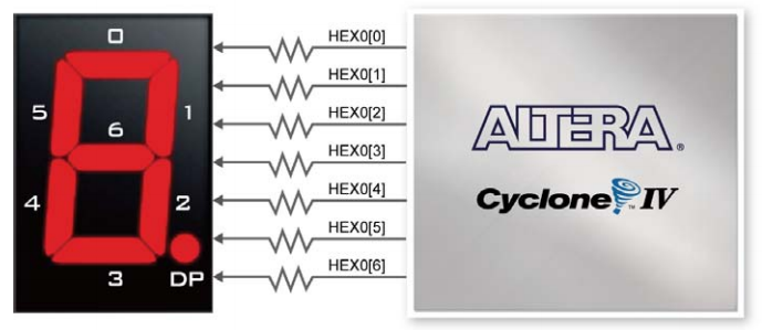
A placa DE2-115 tem oito Display de 7 segmentos. Estes displays são do tipo anodo comum. Eles estão conectados aos pinos do FPGA Cyclone IV conforme mostrado na figura abaixo. A pinagem no FPGA é mostrado na tabela abaixo. Aplicando um nível lógico '0' no pino correspondente fará com que o segmento acenda, enquanto que a aplicação do nível lógico '1' fará com com que ele fique apagado. Cada segmento é identificado com um índice de 0, 1, 2, 3, 4, 5, 6 (que correspondem os segmentos a, b, c, d, e, f, g). O LED do ponto decimal (DP) dos displays não está conectado ao FPGA.
Pinagem dos oito Display de sete segmentos
| Segment | Signal Name | FPGA Pin No. | I/O Standard |
|---|---|---|---|
| a | HEX0[0] | PIN_G18 | 2.5V |
| b | HEX0[1] | PIN_F22 | 2.5V |
| c | HEX0[2] | PIN_E17 | 2.5V |
| d | HEX0[3] | PIN_L26 | Depending on JP7 |
| e | HEX0[4] | PIN_L25 | Depending on JP7 |
| f | HEX0[5] | PIN_J22 | Depending on JP7 |
| g | HEX0[6] | PIN_H22 | Depending on JP7 |
| Segment | Signal Name | FPGA Pin No. | I/O Standard |
| a | HEX1[0] | PIN_M24 | Depending on JP7 |
| b | HEX1[1] | PIN_Y22 | Depending on JP7 |
| c | HEX1[2] | PIN_W21 | Depending on JP7 |
| d | HEX1[3] | PIN_W22 | Depending on JP7 |
| e | HEX1[4] | PIN_W25 | Depending on JP7 |
| f | HEX1[5] | PIN_U23 | Depending on JP7 |
| g | HEX1[6] | PIN_U24 | Depending on JP7 |
| Segment | Signal Name | FPGA Pin No. | I/O Standard |
| a | HEX2[0] | PIN_AA25 | Depending on JP7 |
| b | HEX2[1] | PIN_AA26 | Depending on JP7 |
| c | HEX2[2] | PIN_Y25 | Depending on JP7 |
| d | HEX2[3] | PIN_W26 | Depending on JP7 |
| e | HEX2[4] | PIN_Y26 | Depending on JP7 |
| f | HEX2[5] | PIN_W27 | Depending on JP7 |
| g | HEX2[6] | PIN_W28 | Depending on JP7 |
| Segment | Signal Name | FPGA Pin No. | I/O Standard |
| a | HEX3[0] | PIN_V21 | Depending on JP7 |
| b | HEX3[1] | PIN_U21 | Depending on JP7 |
| c | HEX3[2] | PIN_AB20 | Depending on JP6 |
| d | HEX3[3] | PIN_AA21 | Depending on JP6 |
| e | HEX3[4] | PIN_AD24 | Depending on JP6 |
| f | HEX3[5] | PIN_AF23 | Depending on JP6 |
| g | HEX3[6] | PIN_Y19 | Depending on JP6 |
| Segment | Signal Name | FPGA Pin No. | I/O Standard |
| a | HEX4[0] | PIN_AB19 | Depending on JP6 |
| b | HEX4[1] | PIN_AA19 | Depending on JP6 |
| c | HEX4[2] | PIN_AG21 | Depending on JP6 |
| d | HEX4[3] | PIN_AH21 | Depending on JP6 |
| e | HEX4[4] | PIN_AE19 | Depending on JP6 |
| f | HEX4[5] | PIN_AF19 | Depending on JP6 |
| g | HEX4[6] | PIN_AE18 | Depending on JP6 |
| Segment | Signal Name | FPGA Pin No. | I/O Standard |
| a | HEX5[0] | PIN_AD18 | Depending on JP6 |
| b | HEX5[1] | PIN_AC18 | Depending on JP6 |
| c | HEX5[2] | PIN_AB18 | Depending on JP6 |
| d | HEX5[3] | PIN_AH19 | Depending on JP6 |
| e | HEX5[4] | PIN_AG19 | Depending on JP6 |
| f | HEX5[5] | PIN_AF18 | Depending on JP6 |
| g | HEX5[6] | PIN_AH18 | Depending on JP6 |
| Segment | Signal Name | FPGA Pin No. | I/O Standard |
| a | HEX6[0] | PIN_AA17 | Depending on JP6 |
| b | HEX6[1] | PIN_AB16 | Depending on JP6 |
| c | HEX6[2] | PIN_AA16 | Depending on JP6 |
| d | HEX6[3] | PIN_AB17 | Depending on JP6 |
| e | HEX6[4] | PIN_AB15 | Depending on JP6 |
| f | HEX6[5] | PIN_AA15 | Depending on JP6 |
| g | HEX6[6] | PIN_AC17 | Depending on JP6 |
| Segment | Signal Name | FPGA Pin No. | I/O Standard |
| a | HEX7[0] | PIN_AD17 | Depending on JP6 |
| b | HEX7[1] | PIN_AE17 | Depending on JP6 |
| c | HEX7[2] | PIN_AG17 | Depending on JP6 |
| d | HEX7[3] | PIN_AH17 | Depending on JP6 |
| e | HEX7[4] | PIN_AF17 | Depending on JP6 |
| f | HEX7[5] | PIN_AG18 | Depending on JP6 |
| g | HEX7[6] | PIN_AA14 | 3.3V |
Conexão do LCD
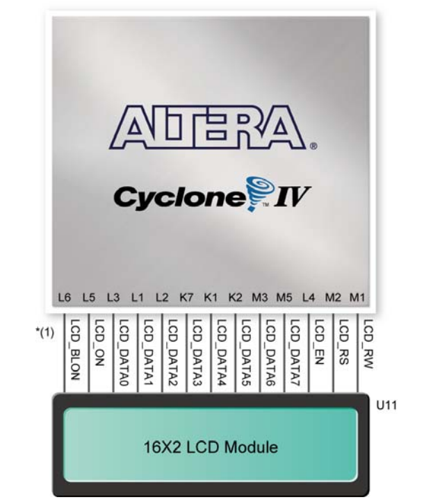
A placa DE2-115 tem um LCD de 2 x 16 caracteres. Ele está conectados aos pinos do FPGA Cyclone IV conforme mostrado na figura abaixo. A pinagem no FPGA é mostrado na tabela abaixo.
O módulo LCD tem um gerador de caracteres que pode ser utilizado para mostrar os textos a partir do envio de comandos adequados para o controlador de display. Informações detalhadas sobre o uso do controlador podem ser obtidas no datasheet do HD44780.
Pinagem LCD
| Signal Name | FPGA Pin No. | I/O Standard |
|---|---|---|
| LCD_DATA[7] | PIN_M5 | 3.3V |
| LCD_DATA[6] | PIN_M3 | 3.3V |
| LCD_DATA[5] | PIN_K2 | 3.3V |
| LCD_DATA[4] | PIN_K1 | 3.3V |
| LCD_DATA[3] | PIN_K7 | 3.3V |
| LCD_DATA[2] | PIN_L2 | 3.3V |
| LCD_DATA[1] | PIN_L1 | 3.3V |
| LCD_DATA[0] | PIN_L3 | 3.3V |
| LCD Enable | PIN_L4 | 3.3V |
| LCD Read/~Write | PIN_M1 | 3.3V |
| LCD LCD Data Select/~Command | PIN_M2 | 3.3V |
| LCD Power ON | PIN_L5 | 3.3V |
| LCD Back Light ON | PIN_L6 | 3.3V |
Conector GPIO
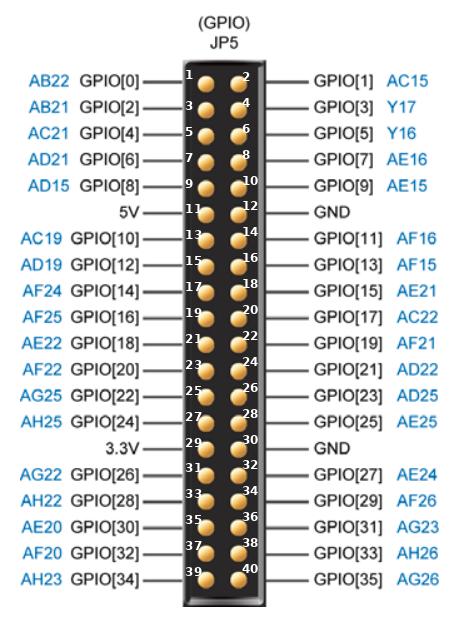
A placa DE2-115 tem um conector (JP5) que tem pinos de entrada e saída propósito geral (General-Purpose Input/Output - GPIO) de 40 pinos que pode ser utilizada para conexão de circuitos externos. A pinagem no FPGA é mostrado na figura abaixo.
- Detalhes importantes
- Cada um dos pinos do conector está ligado a um pinos do FPGA Cyclone IV conforme indicado pelo número de pino em azul na figura acima.
- Os pinos 12 e 30 estão ligados ao GND da placa, o pino 11 está ligado ao 5V e o pino 29 ao 3.3V.
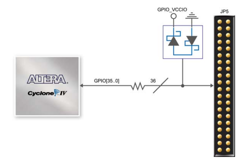
- Todos os demais pinos estão conectados ao FPGA através de um resistor de 47 ohms e com dois diodos zener de proteção conforme mostra a figura abaixo.
- A potência máxima que pode ser consumida dos pinos de alimentação é de 1A em 5V e 1.5A em 3.3V.
- O nivel de tensão os pinos da GPIO pode ser ajustada para 3.3V (default), 2.5V, 1.8V, ou 1.5V usando o jumper JP6. Infelizmente o jumper está sob o acrílico e não pode ser facilmente mudado.
Pinagem da GPIO
| Nr do pino no conector | Nome do sinal | Nr do pino no FPGA |
|---|---|---|
| 1 | GPIO[0] | PIN_AB22 |
| 2 | GPIO[1] | PIN_AC15 |
| 3 | GPIO[2] | PIN_AB21 |
| 4 | GPIO[3] | PIN_Y17 |
| 5 | GPIO[4] | PIN_AC21 |
| 6 | GPIO[5] | PIN_Y16 |
| 7 | GPIO[6] | PIN_AD21 |
| 8 | GPIO[7] | PIN_AE16 |
| 9 | GPIO[8] | PIN_AD15 |
| 10 | GPIO[9] | PIN_AE15 |
| 11 | 5V | NC |
| 12 | GND | NC |
| 13 | GPIO[10] | PIN_AC19 |
| 14 | GPIO[11] | PIN_AF16 |
| 15 | GPIO[12] | PIN_AD19 |
| 16 | GPIO[13] | PIN_AF15 |
| 17 | GPIO[14] | PIN_AF24 |
| 18 | GPIO[15] | PIN_AE21 |
| 19 | GPIO[16] | PIN_AF25 |
| 20 | GPIO[17] | PIN_AC22 |
| 21 | GPIO[18] | PIN_AE22 |
| 22 | GPIO[19] | PIN_AF21 |
| 23 | GPIO[20] | PIN_AF22 |
| 24 | GPIO[21] | PIN_AD22 |
| 25 | GPIO[22] | PIN_AG25 |
| 26 | GPIO[23] | PIN_AD25 |
| 27 | GPIO[24] | PIN_AH25 |
| 28 | GPIO[25] | PIN_AE25 |
| 29 | 3.3V | NC |
| 30 | GND | NC |
| 31 | GPIO[26] | PIN_AG22 |
| 32 | GPIO[27] | PIN_AE24 |
| 33 | GPIO[28] | PIN_AH22 |
| 34 | GPIO[29] | PIN_AF26 |
| 35 | GPIO[30] | PIN_AE20 |
| 36 | GPIO[31] | PIN_AG23 |
| 37 | GPIO[32] | PIN_AF20 |
| 38 | GPIO[33] | PIN_AH26 |
| 39 | GPIO[34] | PIN_AH23 |
| 40 | GPIO[35] | PIN_AG26 |
