Mudanças entre as edições de "ESTE: UART - Serial Communication"
(→Tools) |
|||
| Linha 40: | Linha 40: | ||
==Schematic== | ==Schematic== | ||
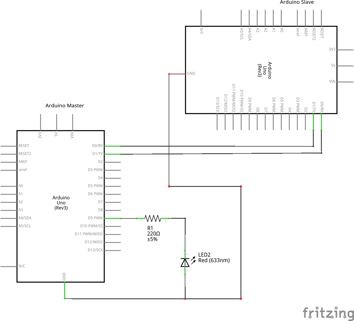
| − | [[Arquivo: | + | [[Arquivo:Uart_2arduinos_AVR_Esquemático.png|600px|thumb|center|Fig. 1 Schematic of the circuit for the AVR microcontroller]] |
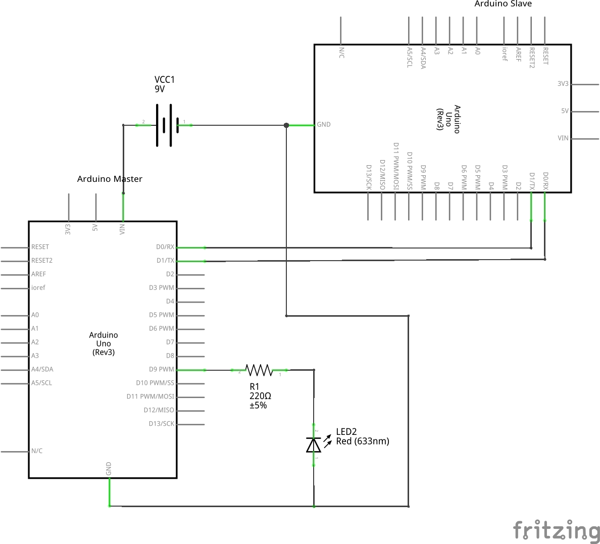
| − | [[Arquivo: | + | [[Arquivo:Uart_2arduinos_IDE_Esquemático.png|600px|thumb|center|Fig. 1.1 Schematic of the circuit for the Arduino IDE]] |
==Part List== | ==Part List== | ||
| Linha 53: | Linha 53: | ||
==Assembly== | ==Assembly== | ||
| − | [[Arquivo: | + | [[Arquivo:Uart_2arduinos_AVR_bb.png|600px|thumb|center|Fig. 2 Assembly of the circuit for the AVR microcontroller]] |
| − | [[Arquivo: | + | [[Arquivo:Uart_2arduinos_IDE_bb.png|600px|thumb|center|Fig. 2.1 Assembly of the circuit for the Arduino IDE]] |
==Solutions== | ==Solutions== | ||
| − | *[C - AVR (master)] | + | *[https://drive.google.com/open?id=0B_chZ-d1CkpCSjdjeTB5T2RDM1E C - AVR (master)] |
| − | *[ UNO (master)] | + | *[https://drive.google.com/open?id=0B_chZ-d1CkpCc0hhNU5HWUpIbUk Arduino UNO (master)] |
| − | *[ C - AVR (slave)] | + | *[https://drive.google.com/open?id=0B_chZ-d1CkpCaklFN2xwQXRUWlk C - AVR (slave)] |
| − | *[ Arduino UNO (slave)] | + | *[https://drive.google.com/open?id=0B_chZ-d1CkpCdlhmYkpNZHhDUXc Arduino UNO (slave)] |
==Tools== | ==Tools== | ||
*[http://cutecom.sourceforge.net/ Cutecom] | *[http://cutecom.sourceforge.net/ Cutecom] | ||
*[https://communities.intel.com/community/makers/drivers Arduino IDE] | *[https://communities.intel.com/community/makers/drivers Arduino IDE] | ||
| + | |||
| + | ==References== | ||
| + | *[http://lab.guilhermemartins.net/2008/12/24/serial-comunication-between-arduinos-with-wire-wireless/ Serial Comunication between Arduinos] | ||
| + | *[http://arduinizando.blogspot.com.br/2013/02/comunicacao-serial-entre-arduinos.html Arduinizando: Comunicação serial entre arduinos] | ||
| + | *[http://harduino.me/2013/11/30/comunicacao-serial-entre-dois-arduinos/ Harduino: Comunicação Serial Entre Dois Arduinos] | ||
| + | *[https://www.youtube.com/watch?v=U1kr9gYviMc Video Tutorial: Microcontroller - AVR ATmega32 - One Way UART Communication with Two Chips] | ||
Edição das 11h47min de 2 de outubro de 2015
This experiment is part of this project.
Here we are going to do an experiment to implement a real aplication with UART. The exercise proposed here is to implement a communication between two boards, namelly two Arduinos Uno. A led on the second arduino(slave board) will blink according to the data received from the first arduino(master board). Therefore we need to programm to types of code: one for the master(sender) board and one for the slave board(receiver). In order to understand all the concepts used in this experiment it is recommended to see at first the basic UART script.
Pseudo code
Let's begin with a solution. The pseudo code of the master an slave boards, respectively, is below:
//master  - sender
int main(void) {
   int num;
   baud_rate = 9600;
   while(1) {
        num = 0;
        println(num);
        delay_2000_ms();
        num = 1;
        println(num);
        delay_2000_ms();
    }
    return 0 ;
}
//slave - receiver
int main(void) {
   int byte_received = 0;
   int baud_rate = 9600;
   int led;
   while(1) {
       if (data_input_field > 0 ) {
           byte_received = read_data_on_input_field();
       }
       led = byte_received;
   }
   return 0;
}
The master pseudo-code always varies a value to be send via the serial port. The slave pseudo-code has a comparison statement to check if the data_input_field is already filled and, if so, we know a data has been sent from the serial port and then the receiver board stores the data on the memory board and turns the led on or off according to the byte_received.
Schematic
Part List
- 1 LED
- 2 Arduinos UNO
- 1 220 ohm resistor
- 1 Protoboard
- 1 9V Batery (just for the Arduino IDE circuit)
- 6 copper wires (tinned) or jumpers


