Mudanças entre as edições de "ESTE: UART - Interrupts and Circular Buffer"
| (20 revisões intermediárias por 2 usuários não estão sendo mostradas) | |||
| Linha 1: | Linha 1: | ||
This experiment is part of [[Embedded_Systems_Experiments_for_the_Telecommunication_Engineering_Course|this project]]. | This experiment is part of [[Embedded_Systems_Experiments_for_the_Telecommunication_Engineering_Course|this project]]. | ||
| + | Here we are going to do an experiment to aprimorate the UART and Interrupts concepts and implement a solution for problems with interrupts. In our last UART application we used the interrupts generated by the income and transmission of data on serial ports. Now we will have two types of interrupts, one for the income of data and one for the transmission of data. For that reason, in each interrupts handler we would need to deal with the income/transmission of bytes and treatment of them among other activities. But these other treatments and routines happen much more slowly when compared to data sending and incoming. Therefore we will handle all these another routines on the main program and we will use the interrupts only for the transmission/reception of bytes. | ||
| + | We also need to store all the data we are receiving or sending by the interrupts temporarily until we handle them on the main program and thus we will use circular buffers to store the data that are going to be sent and received. But why a circular buffer? Circular buffer is extremely useful in buffering serial communication data for some reasons: it makes possible avoid data loss when processing the received data; permits memory to be reusable; is an array that wraps around – where it overwrites old data in the buffer if the microcontroller processing speed is unable to momentarily keep up with the incoming data rate; and is a FIFO (first-in-first-out) buffer. So the exercise here proposed is to send and receive bytes, from the serial port, with the interrupts and handle the data stored on buffers at the main program. | ||
To complete this experiment it is recommended to see at first the [http://wiki.sj.ifsc.edu.br/index.php/ESTE:_UART_-_Basic_Interrupts UART - Basic Interrupts] script. | To complete this experiment it is recommended to see at first the [http://wiki.sj.ifsc.edu.br/index.php/ESTE:_UART_-_Basic_Interrupts UART - Basic Interrupts] script. | ||
| Linha 8: | Linha 10: | ||
<syntaxhighlight lang=c> | <syntaxhighlight lang=c> | ||
| + | |||
| + | // We need 2 buffers, one to store data received from serial, and another to store data that will be sent through the serial | ||
| + | byte rx_buf[BUFFER_SIZE]; | ||
| + | byte tx_buf[BUFFER_SIZE]; | ||
| + | |||
int main(void) { | int main(void) { | ||
| − | + | //Configure serial to 9600 8N1 | |
baud_rate = 9600; | baud_rate = 9600; | ||
| − | while(1) { | + | data_len = 8; |
| − | + | parity = 0; | |
| + | stop_bits = 1; | ||
| + | |||
| + | //Implement loopback application - just remove older byte in the receive queue and enqueue it on the output buffer | ||
| + | while(1) { | ||
| + | if(rx_buffer_has_data()){ | ||
| + | byte aux = pop(rx_buf); | ||
| + | push(tx_buf, aux); | ||
| + | } | ||
} | } | ||
| − | return 0; | + | return 0; |
} | } | ||
| − | + | ||
| − | + | // Finished sending one byte | |
| − | + | tx_interrupt_handler(){ | |
| − | + | byte aux = pop(tx_buf); | |
| − | + | send(aux); | |
| − | + | } | |
| + | |||
| + | // Finished receiving one byte | ||
| + | rx_interrupt_handler(){ | ||
| + | byte aux = receive(); | ||
| + | push(rx_buf, aux); | ||
} | } | ||
</syntaxhighlight> | </syntaxhighlight> | ||
| − | This pseudo-code has a | + | <!-- |
| + | This pseudo-code has a main program with an infinite loop responsable of checking if there are bytes on the rx_buffer - already received from the serial - that may be copied from the rx_buffer to the tx_buffer and later send to the serial port. There ara also interrupt handlers - called by actions/events on the serial port- responsable for each functionality of sending and receiving data. We also have buffers to store bytes received and that are going to be sent and indexes that indicate positions to add new data and catch/fetch old data from the buffers. | ||
| + | The functions we need to have are “stored_transmit” - take data received on rx_buffer and store on tx_buffer -, “stored_receive”- return data from the rx-buffer -, “tx_interrupt_handler” - send data from the tx_buffer to the serial port - and “rx_interrupt_handler”, who adds new data received from the serial port on the rx_buffer. The differences between the indexes we have are the following: The “rx_index_top” has the location where a next incoming byte will be stored. In other words this index always point to 1 location ahead of the last received byte. The “rx_index_down” has the location where the next available data can be fetched/collected and always follow behind “rx_index_top”. Similarly, the “tx_index_top” has the location where a new incoming byte will be stored and the “tx_index_down” has the location where the next available data can be collected and send to the serial port. Also “tx_index_down”, always follow behind “tx_index_top”. | ||
| + | We still need to to clarify that when we have a logic operation as “((rx_index_down + 1) & (buffer_size -1))” it simply means that we will take the atual position of the last byte we want to catch. For example if we have rx_index_down = 0010, buffer_size = 1111, (rx_index_down + 1) = 0011 and then (buffer_size - 1) = 1110 we will do (0011 & 1110) = 0010 and store this value later on rx_index_down to return the correspondent byte in this position. | ||
| + | --> | ||
==Schematic== | ==Schematic== | ||
| Linha 42: | Linha 66: | ||
==Solutions== | ==Solutions== | ||
| − | *[https://drive.google.com/open?id=0B_chZ- | + | *[https://drive.google.com/open?id=0B_chZ-d1CkpCa1lhaEczNjZvOVE C - AVR] |
| − | *[https://drive.google.com/open?id=0B_chZ- | + | *[https://drive.google.com/open?id=0B_chZ-d1CkpCSUdnN0VnNEJsb1E Arduino UNO] |
==Tools== | ==Tools== | ||
| Linha 50: | Linha 74: | ||
==References== | ==References== | ||
| + | <!-- | ||
| + | *[http://db.zmitac.aei.polsl.pl/Electronics_Firm_Docs/ATMEL/Atmel/acrobat/doc1451.pdf Atmel: Using the AVR UART in C] | ||
| + | --> | ||
*[http://www.embarcados.com.br/arquitetura-de-desenvolvimento-de-software-ii/ Embarcados: Arquitetura de desenvolvimento de software] | *[http://www.embarcados.com.br/arquitetura-de-desenvolvimento-de-software-ii/ Embarcados: Arquitetura de desenvolvimento de software] | ||
| − | *[ | + | *[http://leap-embedded-system.com/?p=79 LEAP: An Interrupt Driven Circular Buffer for Serial Communication] |
| − | *[http:// | + | *[http://www.simplyembedded.org/tutorials/interrupt-free-ring-buffer/ Simply Embedded: UART Receive Buffering] |
| − | *[ | + | *[http://www.downtowndougbrown.com/2013/01/microcontrollers-interrupt-safe-ring-buffers/ Downtown Doug Brown: Microcontrollers: Interrupt-safe ring buffers] |
| + | *[http://www.avrfreaks.net/forum/tutsoft-interrupt-driven-uart-receive-ring-fifo-buffer AVR Freaks: Interrupt Driven UART Receive Ring (FIFO) Buffer] | ||
| + | *[https://code.google.com/p/arduino-buffered-serial/ Google Code: Arduino buffered serial] | ||
Edição atual tal como às 08h48min de 3 de novembro de 2015
This experiment is part of this project.
Here we are going to do an experiment to aprimorate the UART and Interrupts concepts and implement a solution for problems with interrupts. In our last UART application we used the interrupts generated by the income and transmission of data on serial ports. Now we will have two types of interrupts, one for the income of data and one for the transmission of data. For that reason, in each interrupts handler we would need to deal with the income/transmission of bytes and treatment of them among other activities. But these other treatments and routines happen much more slowly when compared to data sending and incoming. Therefore we will handle all these another routines on the main program and we will use the interrupts only for the transmission/reception of bytes. We also need to store all the data we are receiving or sending by the interrupts temporarily until we handle them on the main program and thus we will use circular buffers to store the data that are going to be sent and received. But why a circular buffer? Circular buffer is extremely useful in buffering serial communication data for some reasons: it makes possible avoid data loss when processing the received data; permits memory to be reusable; is an array that wraps around – where it overwrites old data in the buffer if the microcontroller processing speed is unable to momentarily keep up with the incoming data rate; and is a FIFO (first-in-first-out) buffer. So the exercise here proposed is to send and receive bytes, from the serial port, with the interrupts and handle the data stored on buffers at the main program. To complete this experiment it is recommended to see at first the UART - Basic Interrupts script.
Pseudo code
Let's begin with a solution. The pseudo code (actual coding is up to you) is below:
// We need 2 buffers, one to store data received from serial, and another to store data that will be sent through the serial
byte rx_buf[BUFFER_SIZE];
byte tx_buf[BUFFER_SIZE];

int main(void) {
    //Configure serial to 9600 8N1
    baud_rate = 9600;
    data_len = 8;
    parity = 0;
    stop_bits = 1;

    //Implement loopback application - just remove older byte in the receive queue and enqueue it on the output buffer
    while(1) {
        if(rx_buffer_has_data()){
            byte aux = pop(rx_buf);
            push(tx_buf, aux);
        }
    }
    return 0;
}

// Finished sending one byte
tx_interrupt_handler(){
    byte aux = pop(tx_buf);
    send(aux);
}

// Finished receiving one byte
rx_interrupt_handler(){
    byte aux = receive();
    push(rx_buf, aux);
}
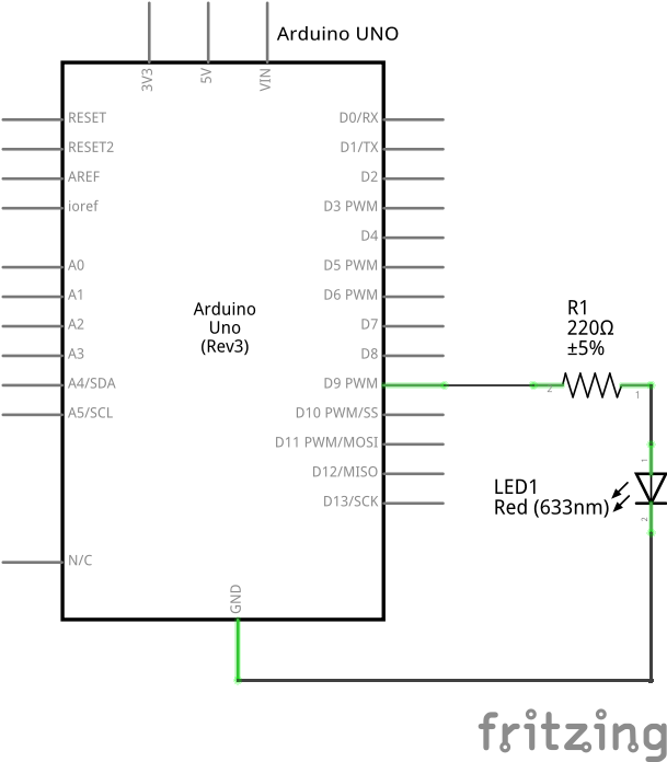
Schematic
Part List
- 1 LED
- 1 220 ohm resistor for the led
- 1 Protoboard
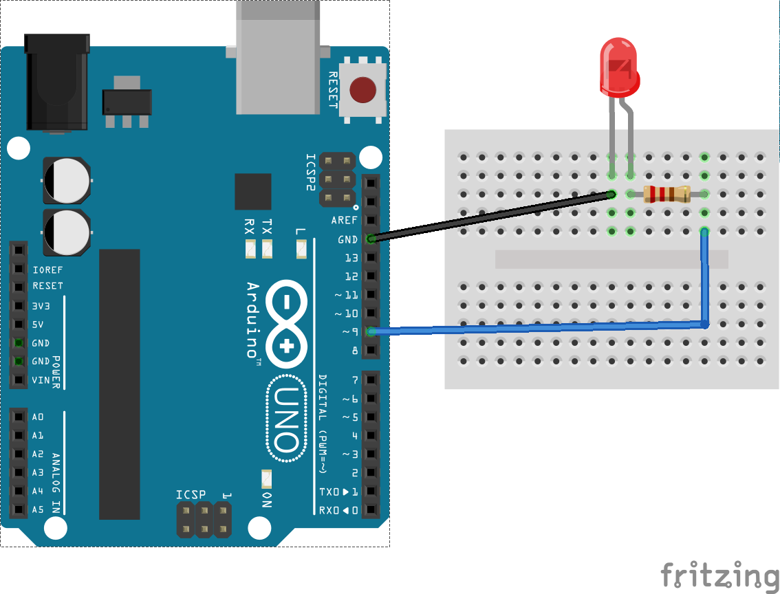
- 2 copper wires (tinned) or jumpers
Assembly
Solutions
Tools
References
- Embarcados: Arquitetura de desenvolvimento de software
- LEAP: An Interrupt Driven Circular Buffer for Serial Communication
- Simply Embedded: UART Receive Buffering
- Downtown Doug Brown: Microcontrollers: Interrupt-safe ring buffers
- AVR Freaks: Interrupt Driven UART Receive Ring (FIFO) Buffer
- Google Code: Arduino buffered serial

