Mudanças entre as edições de "ESTE: UART - Basic Interrupts"
| (2 revisões intermediárias pelo mesmo usuário não estão sendo mostradas) | |||
| Linha 1: | Linha 1: | ||
This experiment is part of [[Embedded_Systems_Experiments_for_the_Telecommunication_Engineering_Course|this project]]. | This experiment is part of [[Embedded_Systems_Experiments_for_the_Telecommunication_Engineering_Course|this project]]. | ||
| − | Here we are going to do an experiment to | + | Here we are going to do an experiment to aprimorate the UART and Interrupts concepts. Until now, for our applications on UART communication we were using the "one-single-loop". This model is quite fast and hardly inserts processing or memory overhead. However, the biggest problem with this architecture is to create routines involving information reading, that generate some kind of delay, and receiving messages. One of the solutions available to solve these problems are the interruptions, that allow a predefined function to be executed whenever an event happens and so, we can program a system that responds to events and not just run their operations sequentially. Among the most common interruptions implemented that will be used in this experiment are the communication one, generated by a reception of a message/byte or when the system is available to send some information. Therefore the exercise here proposed will light up a led - activated by interruption - every time new bytes of data arrive on the serial communication port. To complete this experiment it is recommended to see at first the [http://wiki.sj.ifsc.edu.br/index.php/ESTE:_GPIO_and_External_Interrupts_-_part_1 GPIO and External Interrupts - part 1] and [http://wiki.sj.ifsc.edu.br/index.php/ESTE:_Universal_Assynchronous_Receiver_and_Transmitter_%28UART%29 UART] scripts. |
==Pseudo code== | ==Pseudo code== | ||
| − | Let's begin with a solution. The pseudo code | + | Let's begin with a solution. The pseudo code (actual coding is up to you) is below: |
<syntaxhighlight lang=c> | <syntaxhighlight lang=c> | ||
| − | |||
int main(void) { | int main(void) { | ||
| − | + | byte incomingByte; | |
| − | + | baud_rate = 9600; | |
| − | + | while(1) { | |
| − | + | led_off(); | |
| − | + | } | |
| − | + | return 0; | |
| − | + | } | |
| − | println( | + | void serial_interrupt_event() { |
| − | + | if (data_available_on_input_field()) { | |
| + | incomingByte = read_data_on_input_field(); | ||
| + | println(incomingByte); | ||
| + | led_on(); | ||
} | } | ||
| − | |||
} | } | ||
| − | |||
| − | |||
| − | |||
| − | |||
| − | |||
| − | |||
| − | |||
| − | |||
| − | |||
| − | |||
| − | |||
| − | |||
| − | |||
</syntaxhighlight> | </syntaxhighlight> | ||
| − | + | This pseudo-code has a comparison statement to check if there are data available on the input field of the serial monitor, i.e serial port. If so, the data available will be stored on the memory, printed - only for debuging- and the led will be lighted on. | |
==Schematic== | ==Schematic== | ||
| Linha 51: | Linha 39: | ||
==Assembly== | ==Assembly== | ||
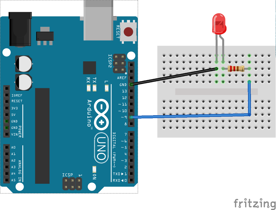
| − | [[Arquivo:Uart_interrupt_basic_bb.png| | + | [[Arquivo:Uart_interrupt_basic_bb.png|450px|thumb|center|Fig. 2 Assembly of the circuit]] |
==Solutions== | ==Solutions== | ||
Edição atual tal como às 09h11min de 15 de outubro de 2015
This experiment is part of this project.
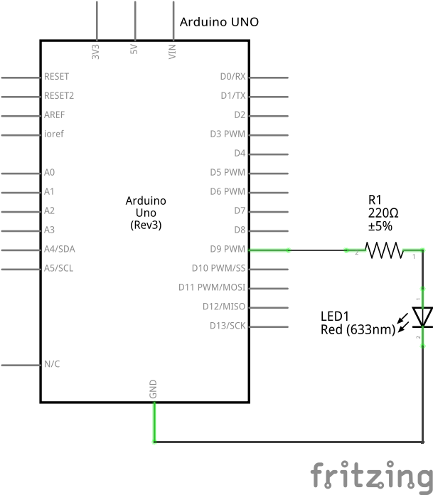
Here we are going to do an experiment to aprimorate the UART and Interrupts concepts. Until now, for our applications on UART communication we were using the "one-single-loop". This model is quite fast and hardly inserts processing or memory overhead. However, the biggest problem with this architecture is to create routines involving information reading, that generate some kind of delay, and receiving messages. One of the solutions available to solve these problems are the interruptions, that allow a predefined function to be executed whenever an event happens and so, we can program a system that responds to events and not just run their operations sequentially. Among the most common interruptions implemented that will be used in this experiment are the communication one, generated by a reception of a message/byte or when the system is available to send some information. Therefore the exercise here proposed will light up a led - activated by interruption - every time new bytes of data arrive on the serial communication port. To complete this experiment it is recommended to see at first the GPIO and External Interrupts - part 1 and UART scripts.
Pseudo code
Let's begin with a solution. The pseudo code (actual coding is up to you) is below:
int main(void) {
    byte incomingByte;
    baud_rate = 9600;
    while(1) {
        led_off();
    }
    return 0;
}
void serial_interrupt_event() {
    if (data_available_on_input_field()) {
        incomingByte = read_data_on_input_field();
        println(incomingByte);
        led_on();
    }
}
This pseudo-code has a comparison statement to check if there are data available on the input field of the serial monitor, i.e serial port. If so, the data available will be stored on the memory, printed - only for debuging- and the led will be lighted on.
Schematic
Part List
- 1 LED
- 1 220 ohm resistor for the led
- 1 Protoboard
- 2 copper wires (tinned) or jumpers

