Mudanças entre as edições de "ESTE: General Purpose Input and Output (GPIO)"
Ir para navegação
Ir para pesquisar
| Linha 25: | Linha 25: | ||
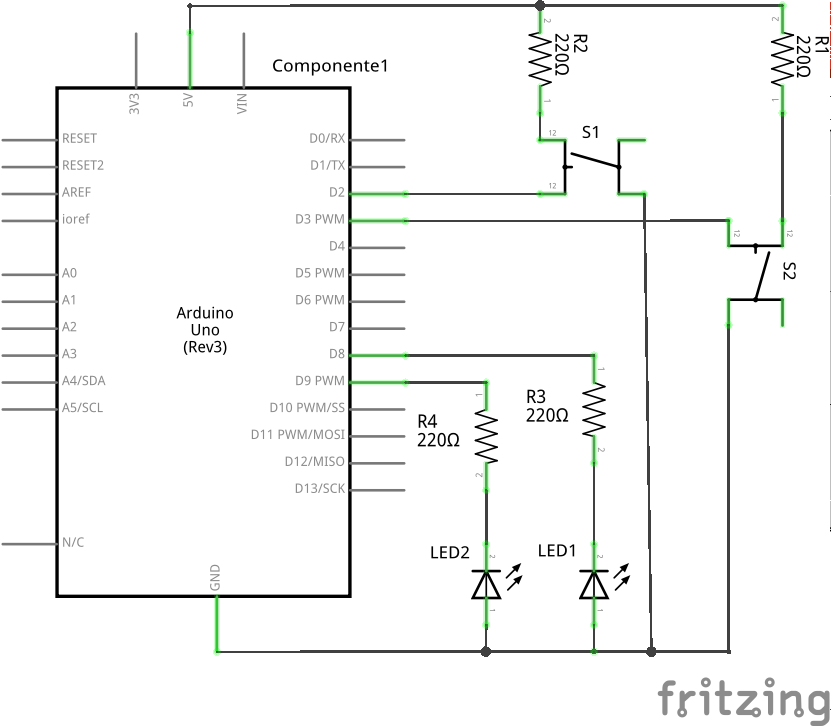
==Schematic== | ==Schematic== | ||
| − | [[Arquivo: | + | [[Arquivo:Led_push_button_Esquemático.png]] |
| + | |||
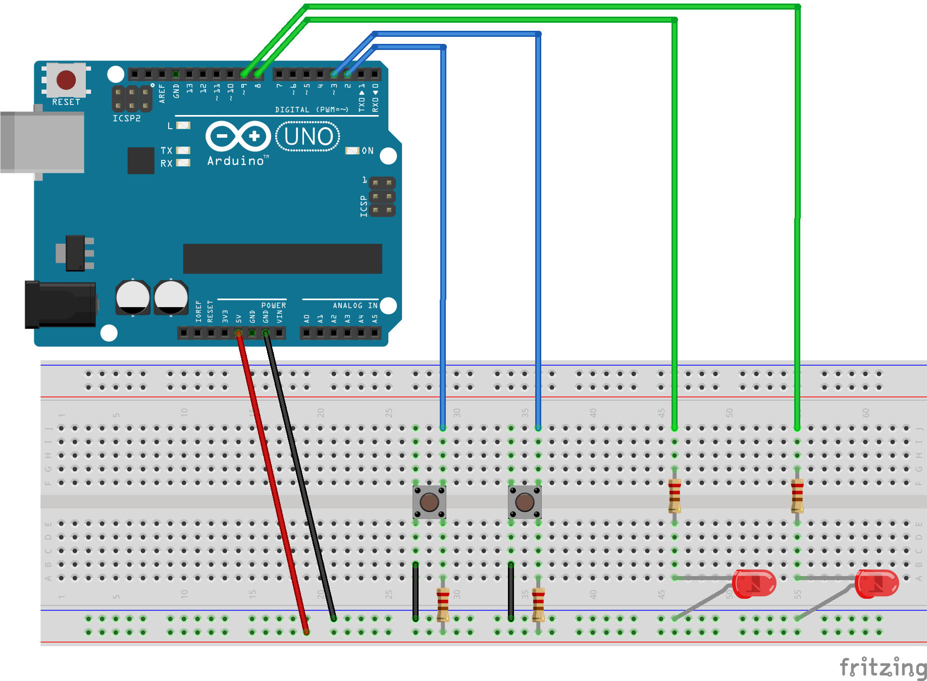
| + | ==Assembly== | ||
| + | [[Arquivo:Led_push_button_bb.png]] | ||
Edição das 17h51min de 15 de setembro de 2015
This experiment is part of this project.
Here we are going to build an experiment with an led and a push button to learn and start using the GPIO. GPIO is called General Purpose Input/Output, and it is basically a group of pins responsable of the communication of input and output digital signals in one board. So the exercise proposed is to turn on and off a led when the push button is pressed or not, respectively.
Pseudo code
Let's begin with a solution. The pseudo code (actual coding is up to you) is below:
int main(void) {
            led_off();
    while(1) {
            if (push_button){
                          led_on();
                   }else{
                  led_off();
           }
    }
    return 0;
}
This pseudo-code has a comparison statement to see if the push button is pressed (1) or not (0). If yes, the led will turn on and if not (else), the led will stay turned off.

