ESTE: Analog Light Sensor (LDR - Light Dependent Resistor)
This experiment is part of this project.
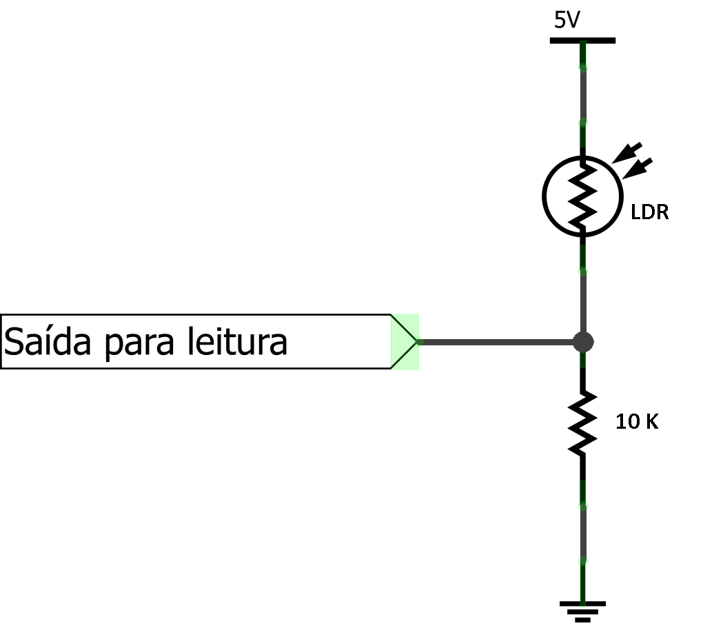
Here we are going to build one experiment to use the ADC and to learn how to use the light sensor (LDR). The LDR is a light sensitive resistor which varies its resistance as the variation in light intensity falling on it. As the light intensity increases (the environment becomes clearer) its resistance decreases to a few tens of ohms, and when the light intensity decreases (the environment becomes darker) its resistance increases for some mega ohms. For starting using this sensor you should have seen the laboraty script “Reading Sensors”. To take the reading output of a light variation, namely the variation of LDR’s resistance, it is necessary to set up a voltage divider, according to the scheme below:
The reading output may be connected to an Arduino in one of its analog inputs (ADC) and to an oscilloscope to check and calculate the RMS (see more on [Sensor Reading’s script]). The resistance of 10k ohms will not necessarily have this value. The value of this resistance should be as close as possible to the initial resistance of the LDR. If the LDR has an initial resistance of 2k ohms you should opt for a resistor of 2.2k ohms. Here we are going to use a resistor of 10K ohms but you must always check the LDR resistance’s value in order to choose an adequate resistor to you circuit.
Pseudo code
Let's begin with a solution. The pseudo code (actual coding is up to you) is below:
int main(void) {
            led_off();
    while(1) {
            if (push_button){
                          led_on();
                   }else{
                  led_off();
           }
    }
    return 0;
}
This pseudo-code has a comparison statement to see if the push button is pressed (1) or not (0). If yes, the led will turn on and if not (else), the led will stay turned off.
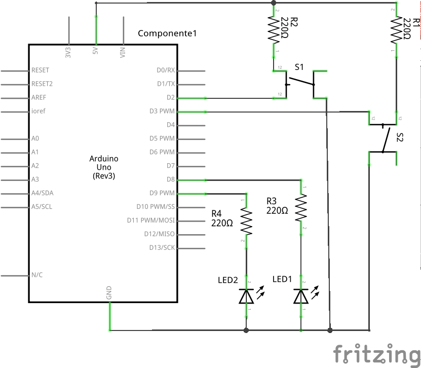
Schematic
Part List
- 2 LED
- 2 Push buttons
- 4 220 ohm resistors
- 1 Protoboard
- 8 copper wires (tinned) or jumpers
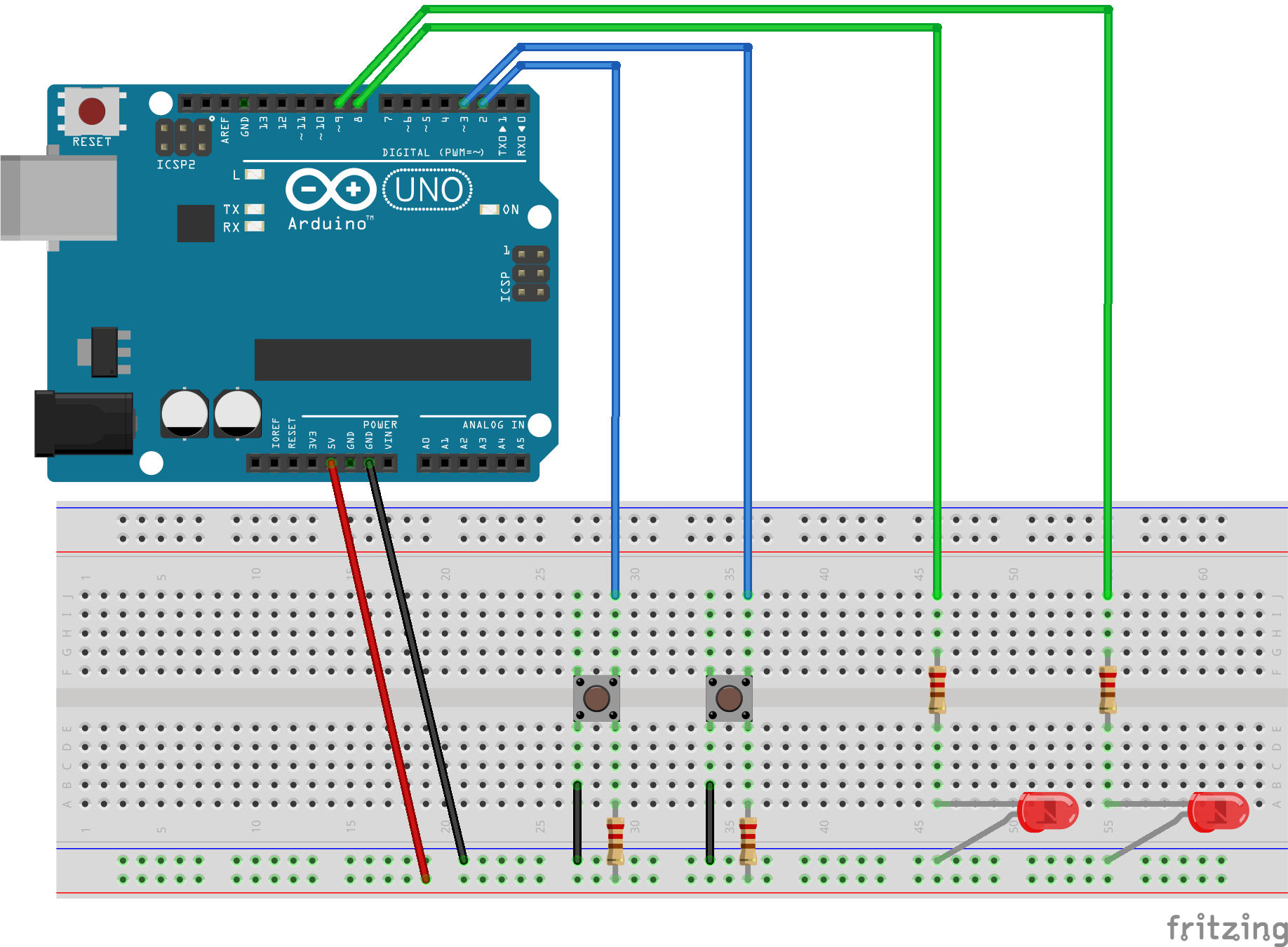
Assembly
Solutions
Tools
- AVR GCC and tools
- Arduino IDE


